Adjustability is Moving Away from the Club Head
I have recently posted about several club manufacturers efforts at developing adjustable shaft stiffness systems (Nike Golf, TaylorMade). This week we get to take a look at an adjustable length system developed by TaylorMade. The design is disclosed in a patent application that published as US Pub. No. 20110081984 titled “Golf Club Shaft,” which describes the invention as:
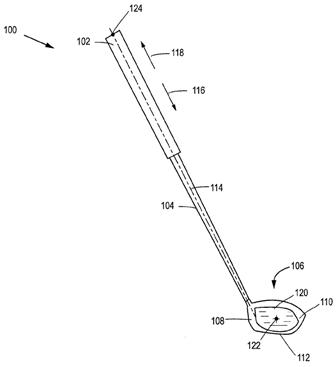
The application explains:
Dave Dawsey - Keeping an Eye on Adjustable Golf Club Inventions
PS – check out more interesting posts on golf club shaft technology HERE
An adjustable length golf club shaft having a grip portion with an end point is disclosed. A locking element is located within the grip portion and a lower shaft having an inner surface that is in frictional contact with the locking element is also disclosed. The locking element is configured to engage the inner surface of the lower shaft. A total length of the golf club shaft is adjustable by a distance of at least one inch and a total weight of the golf club shaft in a weight zone is less than 110 g. The weight zone is defined as a region of the golf club shaft extending from the end point of the grip portion up to 11'' along a central axis of the golf club shaft toward a tip portion of the shaft.


The application explains:
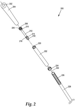
[0041] FIG. 2 illustrates an exploded assembly view of an exemplary adjustable golf club shaft 200, according to one embodiment. The adjustable golf club shaft 200 includes a grip cover 204, a grip end opening 202, an upper housing portion 208, a lower housing portion 210, a drive bolt 206, a drive shaft 212, a stop 216, a locking element 214 or mechanism, a plug 218, an upper shaft 222, an upper shaft keying portion 220, a stop 224, a lower shaft 228, a lower shaft keying portion 226, and a centerline axis 230. The grip cover 204 (being a molded grip) and upper shaft 222 are herein referred to as a "grip portion."Looks like a lot of pieces and parts, but the same could have been said several years ago about the adjustable systems on the market today.
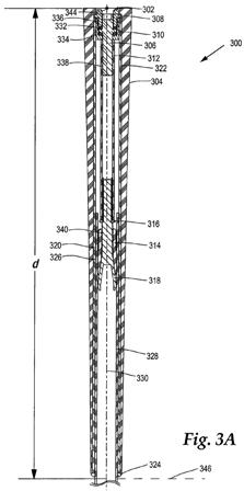
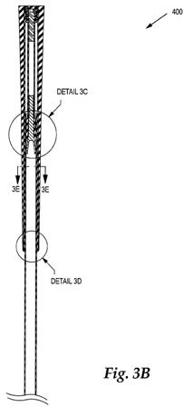
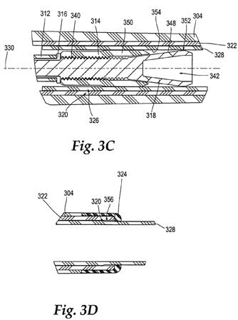
[0042] FIG. 3A shows an assembled cross-sectional view of the adjustable golf club shaft 300 similar to the shaft as shown in FIG. 2. The grip cover 304 envelops an external surface of the upper shaft 322. The upper shaft 322 is coaxially aligned with the lower shaft 328 about the centerline axis 330. The upper shaft 322 and the lower shaft 328 have an overlapping region where the upper shaft 322 telescopically receives the lower shaft 328. The lower shaft 328 is slidably engaged with the upper shaft 322 so that the length of the lower shaft 328 is adjustable with respect to the upper shaft 322. However, an engaged keying region 320 allows the keying portion of the lower shaft 328 to engage with the keying portion of the upper shaft 322 to prevent rotation of the upper shaft about the lower shaft, as will be shown in further detail below.
[0043] In one embodiment, the upper shaft 322 is a graphite or carbon composite material while the lower shaft 328 is also a graphite or composite material. The lightweight construction of the upper shaft 322 and lower shaft 328 allows the weight of the adjustable club to be below a weight threshold.
[0044] FIG. 3A illustrates a grip cover 304, a grip end opening 302, an upper housing portion 308, a lower housing portion 310, a drive bolt 306, a drive shaft 312, a stop 316, a locking element 314, a plug 318, an upper shaft 322, an upper shaft keying portion 320, a stop 324, a lower shaft 328, a lower shaft keying portion 326, and a centerline axis 330, as previously described. The upper shaft keying portion 320 engages with the lower shaft keying portion 326 at a keying interface region. In FIG. 3A, the locking element 314 is shown in a locked position.
[0045] In addition, the upper housing portion 308 and the lower housing portion 310 are threadably engaged in an engagement region 336. The lower housing portion 310 receives the drive bolt 306 before securing the upper housing portion 308 to the lower housing portion 310. The drive bolt 306 further includes a ledge portion that retains the drive bolt 306 within the housing portions 308,310. The ledge portion of the drive bolt 306 is located between an upper washer 332 and a lower washer 334.
.
.
.
[0097] One advantage of the embodiments described herein is that an effective locking element is provided within a shaft that can handle a large amount of rotational or axial force while providing a traditional feel and grip for the golfer. In some embodiments, an axial force of at least 500 N or 2000 N when applied to the longitudinal axis of the shaft does not cause any movement between the upper and lower shaft whatsoever. In addition, the upper and lower shafts can withstand torsional forces of at least 5 N-m to 10 N-m without allowing any movement between the two shafts. In some embodiments, the upper and lower shaft can withstand up to 600 N-m or 700 N-m without failure.
[0098] Another advantage of the embodiments of the present invention is that a relatively low number of turns are required by the user to lock and unlock the locking elements described above. In certain embodiments, less than one full rotation is required to lock or unlock the upper and lower shafts. Thus, a user can easily and quickly adjust the length of the shaft without a large amount of effort.
[0099] Another advantage of the embodiments of the present invention is that a reliable and effective arrangement is provided to efficiently lock and unlock an upper and lower shaft. In embodiments where the upper shaft is a composite material, a lightweight adjustable grip portion is described herein. In addition, the components described herein are produced and assembled to be free of rattle and noise that might be undesirable to a user.
[0100] Furthermore, another advantage of the embodiments of the present invention is that an adjustable shaft is provided that aesthetically looks normal to a user on the exterior. The adjustable shaft can also be re-gripped with a standard or oversized replacement grip after the original grip is worn or no longer desired.
[0101] Another significant advantage of the embodiments described herein is that the grip appears "normal" in appearance and weight while providing a lightweight locking system. Minimizing weight is an advantage and therefore carbon fiber, aluminum, titanium, magnesium, and plastic would be used were strength and durability requirements allow. The present embodiments minimize overall weight by having the anti-rotation or keying features integrally incorporated into the grip. If an underlisting type grip is used, a rigid plastic or molded composite piece can be made with anti-rotation features and an additional sliding tube will not be necessary. Thus, the overall part count and weight are reduced within a weight zone.
[0102] Any of the embodiments described herein can be configured to have any total club length. For example, a total club length of the embodiments described herein can be adjusted to about 1092.2 mm (43''), 1117.6 mm (44''), 1143 mm (45''), 1168.4 mm (46''), 1193.8 mm (47''), or 1219.2 mm (48''). In one embodiment, the length of the club can be a length in the range of about 38'' to 48''.
Dave Dawsey - Keeping an Eye on Adjustable Golf Club Inventions
PS – check out more interesting posts on golf club shaft technology HERE

Comments