Introducing the Gravity Core by Cobra Golf!
Yep, that’s right, Cobra Golf, not Callaway Golf. Why am I posting this? Dumb luck. A Cobra Golf patent application published today while I was working on another post regarding vertical center of gravity adjustment systems in light of this week's launch of the Big Bertha.
Let's be honest, the word “innovation” is thrown around way too loosely in the golf industry. In fact, if you work in the golf industry and ever catch yourself starting to say “this is the first club to…,” or “our new innovation…”, then you should really demote yourself because eventually someone will call you out. Plus it makes you sound like you are on an infomercial and kills your credibility! After all, golfers have been tinkering with clubs since the first worm-burner.
Sure, there are lots of elegant solutions found in today’s club designs, and there is no doubt they required a lot of creativity and engineering hours, but there are very few real innovations. Later this week I will illustrate that vertical center of gravity adjustability was indeed an innovation back in 1922, not 2013! In fact in the past I have posted on other recent vertical center of gravity adjustment designs, but today let’s take a look at Cobra Golf’s solution to vertical center of gravity adjustment.
The patent application published today as US Pub. No. 20130324299 titled “Golf Club with Vertically Adjustable Center of Gravity,” which describes the invention as:
The application discloses all sorts of variations and I have included a few favorites below (not necessarily my favorites, or favorites of Callaway Golf; just favorites).
Check back often for my post on the 1922 innovation of vertical center of gravity adjustability!
Dave Dawsey - The Golf Attorney :: Follow me on Twitter at @GolfPatents
PS - Turns out the application also discloses a waffle maker, check out this iron! Would love to see it in the 2015 product line-up.
Let's be honest, the word “innovation” is thrown around way too loosely in the golf industry. In fact, if you work in the golf industry and ever catch yourself starting to say “this is the first club to…,” or “our new innovation…”, then you should really demote yourself because eventually someone will call you out. Plus it makes you sound like you are on an infomercial and kills your credibility! After all, golfers have been tinkering with clubs since the first worm-burner.
Sure, there are lots of elegant solutions found in today’s club designs, and there is no doubt they required a lot of creativity and engineering hours, but there are very few real innovations. Later this week I will illustrate that vertical center of gravity adjustability was indeed an innovation back in 1922, not 2013! In fact in the past I have posted on other recent vertical center of gravity adjustment designs, but today let’s take a look at Cobra Golf’s solution to vertical center of gravity adjustment.
The patent application published today as US Pub. No. 20130324299 titled “Golf Club with Vertically Adjustable Center of Gravity,” which describes the invention as:
The invention generally relates to golf clubs with adjustable mass properties. In certain aspects, the invention provides methods and mechanisms for adjusting a club head center of gravity in a vertical direction. Changing a center of gravity in the vertical direction can be done without substantially changing the center of gravity in other directions.
The application discloses all sorts of variations and I have included a few favorites below (not necessarily my favorites, or favorites of Callaway Golf; just favorites).

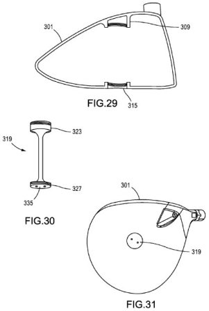
[0101] FIG. 29 shows a club head 301 configured to receive a weight member 319. Club head 301 preferably includes an internal boss 309 to receive and stabilize a location of weight member 319 and a surface-exposed boss 315. Either or both of internal boss 309 and surface boss 315 may include a mechanism to mate with a portion of weight member 319. Any suitable mechanism may be included such as a snap-fit tab or tabs, a threaded interface, press-fit parts, or other.
[0102] FIG. 30 shows weight member 319 for insertion into club head 301 to provide a position of a center of gravity that is adjustable in a vertical direction. Weight member 319 preferably has a non-uniform density. For example, weight member 319 may include a heavy portion 323 and a light portion 327 (e.g., at opposed ends of weight member 319) and the heavy portion could weigh more (e.g., anywhere from 1 to 10 grams more). In certain embodiments, one end of member 319 weights about 6 to 9 grams more than the other end (e.g., if you cut member 319 in half at the middle and weight each half separately). Weight member 319 may also include a tool interface surface 335. Club head 301 may be used with a plurality of members 319 that have different weight properties (e.g., a set or kit).
[0103] FIG. 31 shows club head 301 having weight member 319 installed therein. In some embodiments, weight member 319 may be installed and removed by using a tool on tool interface surface 335 (e.g., to unscrew member 319 at threaded ends from bosses 309 and 315). In certain embodiments, member 319 is a screw that may be inserted from the sole to connect to a boss on the interior surface of the crown. Surface boss 315 can have a smooth bore (e.g., with an internal diameter large enough for an end of screw 319 to pass through, such that screw 319 attaches to club head 301 only at internal boss 309.

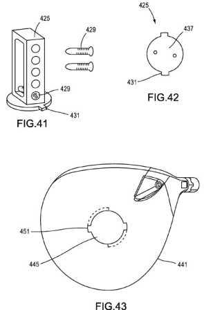
[0108] FIGS. 41-43 illustrate a club head 441 that embodies an adjustable center of gravity concept in which a cartridge 425 with multiple weight ports can be inserted and removed from a receiving chamber 445 in club head 441. Weight slugs 429 can be selectively inserted into the weight ports, and cartridge 425 can be inserted and locked into club head 441.
[0109] In certain embodiments, cartridge 425 includes a tool engagement surface 437. Cartridge 425 and receiving chamber 445 may interact through a combination of tabs 431 and slots 451 (which may each be on either of cartridge 425 and receiving chamber 445). Club head 441 can be caused to have a center of gravity with a different height when the club head is at address by removing and interchanging slugs 429 in cartridge 425.

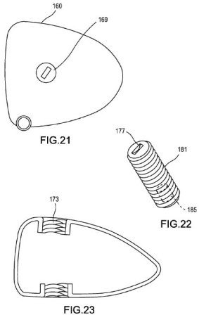
[0087] FIGS. 21-23 show a mechanism for adjusting a center of gravity of a club head in a vertical direction. Club head 160 includes one or more of threaded bore portion 173. Threaded member 181 can be mounted in club head 160 by threading it through bore portion 173.
[0088] In some embodiments, threaded member 181 is generally made to include a low or neutral density material such as a plastic or a composite. In certain embodiment, to facilitate insertion or removal of member 181, it includes a low-friction material such as a polymer like PTFE. Positioning member 181 in club head 160 can adjust a center of gravity of the club head in a vertical direction. For example, member 181 can include a weight mass 185 located at an off-center position. A golfer can mount member 181 in club head 160 in either orientation to change a vertical center of gravity. Further, a club head 160 can be provided with one of or a set of member 181. In a set, each of member 181 can include different mass distribution properties. For example, weight mass 185 can be progressively more distant from a center of member 181 within members of a set.

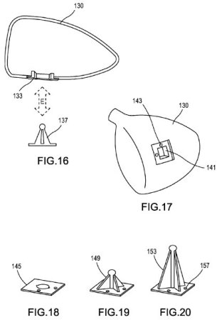
[0084] FIG. 16 shows a club head 130 and weight pylon 137. Arrow E indicates how pylon 137 may be mated with or removed from club head 130. Viewing FIG. 17 in conjunction with FIGS. 18-20, it will be appreciated that a weighting pylon may be mounted in mount hole 141 on a portion of club head 130 (here, hole 141 is shown in a sole). While hole 141 may be at any position on club head 130, when it is on a sole, FIG. 18 shows a low CG pylon 145. FIGS. 18 and 20 show an intermediate CG pylon 149 and a high CG pylon 153, respectively. A CG pylon may be positioned in club head 130 by inserting it through hole 141.
[0085] In some embodiments, hole 141 includes one or more of a set hole 143 configured to match to mounting mechanism 157 on a base of a pylon. Mounting mechanism 157 can include a hole and a screw that threads through the pylon into hole 143. In certain embodiments, mounting mechanism 157 on a pylon is a barbed pointer that clips through hole 143.
[0086] One benefit of the mechanism for adjusting vertical center of gravity as shown in FIGS. 16-20 is that the mass of club head 130 is limited to the sole, crown, face plate, etc.--the positions on a club head where the mass would be anyway. Because a pylon protrudes into the free space of club head 130, and is not surrounded by the material of an indention in club head 130, a golfer is given maximum control over a vertical position of the center of gravity.

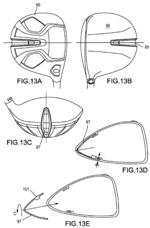
[0079] FIG. 13A-13E show a club head 90 with a repositionable, interchangeable bent strap 97 having weight mass 101. Similar to that shown in FIGS. 12A-12E, bent strap 97 can be removably coupled to club head 90 via one or more of a press-fit slot, set screw, adhesive, Velcro, snap-fit retention mechanism, or similar, or a combination thereof. As shown by arrow C, bent strap 97 can be attached in multiple orientations to adjust a center of gravity of club head 90 in a vertical direction.

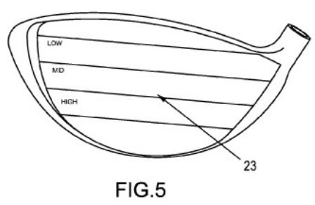
[0070] FIG. 5 illustrates areas of a face of a club. Without being bound by any particular mechanism of action, it may be theorized that lowering a vertical center of gravity tends to shift which region of a face (low, med, or high) transfers momentum to or makes contact with a ball during a shot. Hits from a lower part of the club head face may go high and be more forgiving. Hits from a top portion of the club face (here labeled low) may tend to drive the ball forward, favoring long-distance shots.
Check back often for my post on the 1922 innovation of vertical center of gravity adjustability!
Dave Dawsey - The Golf Attorney :: Follow me on Twitter at @GolfPatents
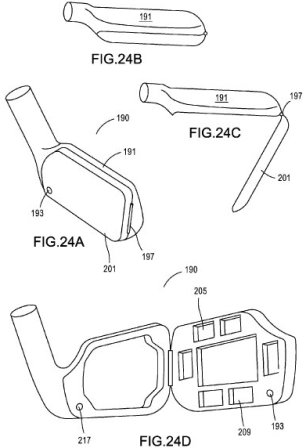
PS - Turns out the application also discloses a waffle maker, check out this iron! Would love to see it in the 2015 product line-up.


Comments