Sneak Peek at the Cobra Catamaran Driver
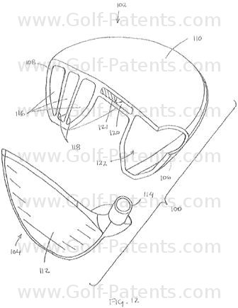
OK, I made up the “catamaran” name and “sneak peek” might be a bit of a stretch because it is generally used in association with a product that will actually make it to market. Ignoring those minor details, Cobra Golf did have a rather interesting patent application publish today as US Pub. No. 20110256954 titled “Golf Club with Multi-Component Construction.” Check out this driver design.
The application explains:
A hinged face! Pretty interesting stuff but will it ever see the light of day?
Dave Dawsey - Monitoring Golf Patent Applications


The application explains:
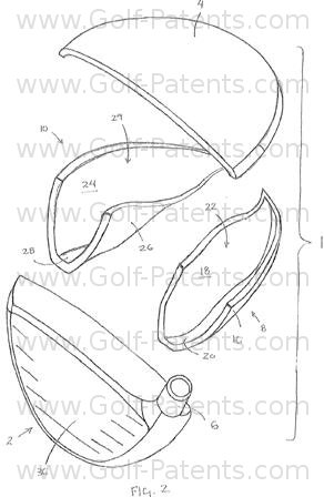
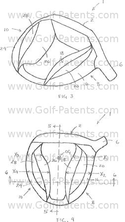
[0031] Referring first to FIGS. 1-6, a golf club head including a construction of the present invention will be described. Golf club head 1 generally includes a face body member 2 that includes a forward ball-striking surface, a crown 4, a hosel 6, a heel body member 8 and a toe body member 10. Rather than having a sole surface that generally matches the plan area of the crown, club head 1 includes an unconventional construction by including a raised central body portion of the golf club head and elongate lateral sole portions, or pontoons, formed by heel body member 8 and toe body member 10 that combine to define a central cavity on the underside of the club head that is opened downward.Now this is the part that I find most interesting…
.
.
.
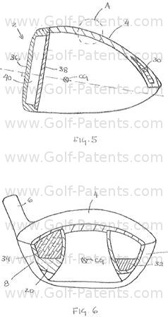
[0036] In the present embodiment, crown 4 forms the raised central body portion 13 and extends between heel body member 8 and toe body member 10 to rigidly couple the body portions. From above, crown 4 includes a continuous bulbous top surface so that when golf club head 1 is placed in an address position by a golfer it provides the appearance of a conventional golf club head. Crown 4, as shown in FIGS. 5 and 6, is constructed in a first configuration in which crown 4 includes a thickness and is constructed from a selected material to provide the desired structural rigidity. Additionally, a lower surface of crown 4 also forms the lower surface of the raised central body portion 13. Because of that construction, a center of gravity of golf club head 1 is located within the central cavity, below central portion 13, and outside of an envelope defined by the outer surfaces of club head 1. In particular, the center of gravity is located below the lower surface of crown 4 and between heel body member 8 and toe body member. Preferably, an axis of percussion B, i.e., an axis extending from the ball-striking face orthogonally and through the center of gravity, does not intersect a sole surface of the club head. As used herein, "sole surface" refers to the lowermost downward facing surface of the club head, which may be the lower surface of a crown member or a lower surface of a sole member depending on the particular construction. As a result a central portion of the sole surface is substantially above a center of percussion of the golf club head. As a result, the rigidity of the face is not increased significantly by the central portion.
[0037] The structure of golf club head 1 provides ground contacting surfaces on both of heel body member 8 and toe body member 10 and concentrates the mass of the club head toward the heel and toe. As a result, the stability of the club head during address is increased and the moment of inertia of the club head may be more easily manipulated while the face may remain flexible to optimize the coefficient of restitution.


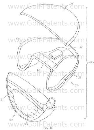
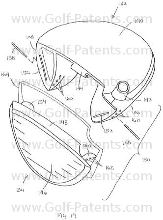
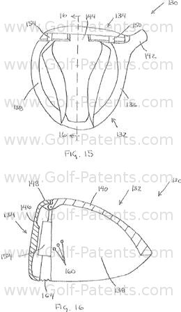
[0053] Face member 134 is coupled to body member 132 so that they may be rotated relative to each other. In particular, the relative rotation is effectuated by a hinge 144 that couples body member 132 and face member 134. Hinge 144 includes mating portions on an underside of crown 140 and on face perimeter that engage each other and allow relative rotation between body member 132 and face member 134 about an axis that generally extends in a heel to toe direction. Alternatively, the hinge may be oriented to provide relative rotation between the body member and the face member along an axis that extends vertically so that the face angle may be adjusted independent of loft angle and lie angle. Still further, a plurality of hinges may be provided, for example one oriented to rotate about a heel to toe axis and another oriented to rotate about a vertical axis to provide adjustment of both loft angle and face angle.
[0054] Golf club head 130 also includes a hinge locking mechanism that retains body member 132 and face member 134 in a particular relative orientation. Preferably, the locking mechanism is configured to retain the components so that golf club head 130 is configured to have a plurality of predetermined lofts. For example, the locking mechanism may be constructed so that the golf club head can be configured with a loft angle of 8.5 degree, 9.5 degree, or 10.5 degree. The incremental change may be selected to be a constant change, such as 1 degree between each position, or the change may vary between positions. Preferably, the amount of each incremental angular change is between about 0.1 degree and about 1 degree. It should be appreciated that any number of positions may be provided.
[0055] In the present embodiment, the locking mechanism includes tabs attached to face member 134 that are received in cavities of body member 132 and anchored in place by pins 158. In particular, a heel tab 150 extends from a heel end of face member 134, rearward toward body member 132, and is slidably received in a heel cavity 152 of body member 132. Similarly, a toe tab 154 extends from a toe end of face member 134, rearward toward body member 132, and is slidably received in a toe cavity 156.
[0056] Body apertures 160 extend through portions of body member 132 and intersect heel cavity 152 and toe cavity 156. When the face member is in one of the predetermined orientations, corresponding tab apertures 162 align with body apertures 160 so that pins 158 may be inserted. When inserted, each pin extends across the sliding interface between the tab and cavity so that relative motion is prevented.
[0057] An optional gasket 164 may be provided to conceal or fill the gap created by the hinged interface between body member 132 and face member 134. Gasket 164 may also be configured to act as a dampener to reduce any "slop" presented by the hinged interface. Preferably, gasket is constructed from any flexible, rubber-like material.
A hinged face! Pretty interesting stuff but will it ever see the light of day?
Dave Dawsey - Monitoring Golf Patent Applications

Comments