Do Golfers Need More Driver Adjustability?
When is too much of a good thing a bad thing, and has adjustability hit this threshold?
The reason I ask is because Nike had an interesting patent application publish this week directed to an "adjustable ball striking face." The application published as US Pub. No. 20110207552 and describes the invention as:

The application explains:
Any chance this design will ever make it to the market? Looks like a bunch of heavy components to me.
Dave Dawsey - Monitoring Adjustable Golf Club Inventions
The reason I ask is because Nike had an interesting patent application publish this week directed to an "adjustable ball striking face." The application published as US Pub. No. 20110207552 and describes the invention as:
This invention relates generally to golf clubs or golf club heads, having an adjustable ball striking face. The golf club head includes a club head body, a ball striking face, and a brace extending from a sole of the club head body to an inner surface of the ball striking face. The brace may further include an end portion engaged with the inner surface of the ball striking face, a fixed rod located between the end portion and an inner surface of the club head at the sole, a biasing member attached to the fixed rod. The biasing member may provide a biasing force to the ball striking face such that the ball striking face is adjustable between a first direction thereby adjusting a face angle of the club head and a second direction thereby adjusting a loft angle of the club head.Check this out!


The application explains:
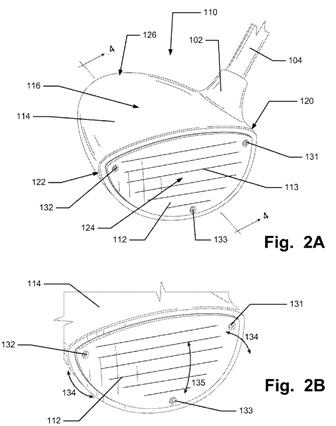
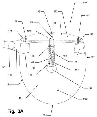
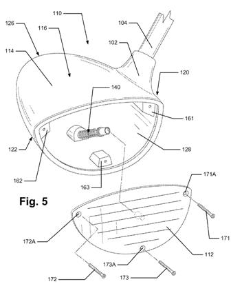
[0051] The golf club heads 110 shown in FIGS. 2A through 12 contain many common features, which are referenced by similar reference numerals in the description below. As shown in FIGS. 2A-5, the club head 110 generally includes a ball striking face 112, a club head body 114, and at least one brace 140. The at least one brace 140 may be attached to or engaged with the ball striking face 112 and/or the club head body 114. The brace 140 may provide support to the ball striking face 112 such that the ball striking face 112 may be adjusted left or right (for hook and slice) or up and down (for loft and de-loft). This adjustability feature may allow a golfer to adjust the direction of the ball upon impact by adjusting the angle and orientation of the ball striking face 112 which strikes the ball.
.
.
.
[0054] Additionally, the golf club head 110 may include a face engaging area. In an example according to aspects of this invention, as illustrated in FIGS. 3A through 5, the face engaging area may include a plurality of support blocks 161 162 163. The support blocks 161 162 163 may be engaged with or attached to the inner body surfaces 136 and extend from the perimeter of the club head inner body surfaces 136. The support blocks 161 162 163 may be configured to support the ball striking face 112, when the ball striking face 112 is attached to the club head body 114. Additionally, as described more below, the support blocks 161 162 163 may include attachment means for the ball striking face 112, such as screw holes, etc. The support blocks 161 162 163 may be manufactured as an integral component to the club head body in accordance with aspects of this invention. In another embodiment in accordance with this invention, the support blocks 161 162 163 may also be manufactured as separate parts that may be attached to the club head body 114. The support blocks 161 162 163 may be attached to the club head body 114 in any one of various "engaging" techniques known and used in the art, such as: bonding using adhesives or cements; engaging using welding, brazing soldering, or other fusing techniques; attachment using mechanical connectors including user releasable connectors (such as screws, bolts, nuts, or the like); and the like. The support blocks 161 162 163 may include one or more metal alloys.
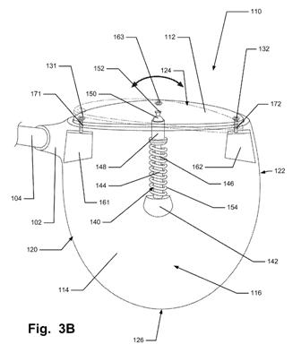
[0056] In the illustrated embodiment shown in FIGS. 2A and 2B, the ball striking face 112 of a given club head 110 has a face angle. The face angle is the angle of the ball striking face 112 of the club head 110 relative to the target. If the club head 110 is "square" or with a face angle at zero degrees, the ball striking face 112 will be directly facing the target on address. FIG. 3A illustrates a ball striking face 112 of the club head that has a "square" face angle. If the club head 110 is "closed" or with a face angle of minus degrees, the ball striking face 112 will be aligned to the left of the target (for right-handed players; the opposite is true for left-handed players). If the club head 110 is "open" or with a face angle of positive degrees, the ball striking face 112 will be aligned to the right of the target (for right-handed players; the opposite is true for left-handed players). As will be discussed further below, the face angle of the ball striking face 112 of the present invention may be adjusted in accordance with this invention. For example, in accordance with at least some examples of the invention, the face angle of the ball striking face 112 may be adjusted (either positive or minus) by at least approximately 1 degree. In another embodiment in accordance with at least some examples of the invention, the face angle of the ball striking face 112 may be adjusted (either positive or minus) by at least approximately 3 degrees. In another embodiment in accordance with at least some examples of the invention, the face angle of the ball striking face 112 may be adjusted (either positive or minus) by at least approximately 5 degrees. FIG. 3B illustrates an example club head 110 with the ball striking face 112 adjusted for face angle, specifically, with the ball striking face 112 with an open, or positive face angle.
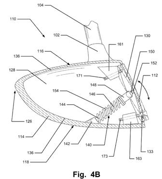
[0057] Additionally, in the illustrative embodiment shown in FIGS. 2A and 2B, the ball striking surface 113 is inclined slightly (i.e., at a loft angle), to give a golf ball slight lift and spin when struck. Generally, the loft angle is the main determining factor in golf ball trajectory. FIG. 4A illustrates the ball striking face 112 with a loft angle with no adjustments. The loft angle of a ball striking face 112 can be varied to effect the trajectory, distance, backspin, and roll of a golf ball struck by a club head 110. As will be discussed further below, the loft angle of the ball striking face 112 of the present invention may be adjusted in accordance with this invention. For example, in accordance with at least some examples of the invention, the loft angle of the club head 110 may be adjusted (increased or decreased) by at least approximately 2 degrees. In another embodiment in accordance with at least some examples of the invention, the loft angle of the club head 110 may be adjusted (increased or decreased) by at least approximately 4 degrees. In another embodiment in accordance with at least some examples of the invention, the loft angle of the club head 110 may be adjusted (increased or decreased) by at least approximately 6 degrees. FIG. 4B illustrates an example club head 110 with the ball striking face 112 adjusted for loft angle, specifically, increasing the loft angle.
[0058] Additionally, the face angle and the loft angle of the ball striking face 112 may be adjusted in combination together. For example, the face angle may be adjusted with an open or positive face angle and the loft angle may be increased in combination with each other. In another example, the face angle may be adjusted with a closed or negative face angle and the loft angle may be decreased in combination with each other. Any combination of the face angle and the loft angle of the ball striking face 112 may be utilized without departing from this invention.
[0059] As illustrated in FIGS. 2A and 2B, the ball striking face 112 may include a plurality of adjustment points 131 132 133 which may allow a user or club fitter to adjust the loft angle and face angle. Each adjustment point may include a screw 171 172 173 and a corresponding screw hole 171A 172A 173A located in the ball striking face 112. In accordance with other examples of this invention, the adjustment point 131 132 133 may include additional or different means of adjusting the loft angle and face angle as presently known in the art, such as set screws, bolts, or other mechanical connectors as known and used in the art. Additionally, these set screws, bolts, or other mechanical connectors may include female heads such as known and used in the art, for example Phillips heads or star-torque heads, etc. As specifically illustrated in the example club head 110 in accordance with this invention in FIG. 2A, the ball striking face 112 includes a first adjustment point 131, a second adjustment point 132, and a third adjustment point 133. The first adjustment point 131 may be located approximately at the high-heel area 122 of the ball striking face 112. The second adjustment point 132 may be located approximately at the high-toe area 120 of the ball striking face 112. The third adjustment point 133 may be located approximately between the low-heel area 122 and the low-toe area 120 of the ball striking face 112.
[0060] As illustrated in the embodiment of the golf club heads 110 shown in FIGS. 3A through 5, the club head 110 may also include a brace system or brace 140. The brace 140 could also be identified or referenced as a support member. In this example golf club head 110, the brace 140 may extend from an inner surface 136 of the club head body 110, across at least a portion of the cavity 128, to the inner surface 130 of the ball striking face 112. In the example golf club head 110 illustrated in FIG. 4A, the brace 140 extends from the sole of the club head body 114 to the inner surface 130 of the ball striking face 112. In other structures, the brace 140 may extend from a different one of the inner surfaces 136 of the body 114, for example, from the top 116 to the inner surface 130 of the ball striking face 112. The golf club head 110 need not have an inner cavity, or the inner cavity 128 may be filled with another material, and the brace 140 may extend across or through a solid material or a filler material between the inner body surface 136 and the ball striking face 112.
[0061] The brace 140 may extend to and contact the sole 118 or top 116 of the golf club head 110 at any desired position without departing from this invention, provided the brace 140 is positioned and oriented (or angled) to provide the desired supporting or bracing and adjustable functions. The brace 140 may extend to and contact the sole 118 by being integrally formed or contacted with the sole 118. In another embodiment in accordance with this invention, the brace may extend to and contact the sole 118 at a sole engagement portion 142. The sole engagement portion 142, as illustrated in FIG. 4A, may be attached to the sole 118 or top 116 of the golf club head 110. Additionally the sole engagement portion 142 may provide the brace 140 an engagement area to contact the sole 118 or top 116 of the club head 110. The sole engagement portion 142 may include a receptacle to receive the brace 140. Additionally, the sole engagement portion 142 may include other attachment means known and used in the art.
.
.
.
[0063] In the golf club head 110 shown in FIGS. 3A through 4B, the brace 140 may include a fixed rod 144, an end portion 152, and a biasing member 154. The end portion 152 may be connected to or engaged with the inner face surface 130 to form a contact point between the brace 140 and the ball striking face 112. The fixed rod 144 may be located between the end portion 152 and the inner surface 136 of the club head 110, with the biasing member 154 surrounded outside a portion of or the entire fixed rod 144. In an alternate embodiment in accordance with this invention, the fixed rod 144 may be located between the end portion 152 and the biasing member 154. The biasing member 154 may provide a biasing force to the ball striking face 112 such that the ball striking face 112 may be adjustable to a user.
[0064] Furthermore, the fixed rod 144 may also include a retractable rod 146 located within or extending from the fixed rod 144. The retractable rod 146 may be attached to the biasing member 154 such that the retractable rod 146 may retract into the fixed rod 144 when pressure is placed against the ball striking face 112 (such as when a ball contacts the ball striking face 112). The fixed rod 144 and the retractable rod 146 may be made of materials known and used in the art, such as metals or plastics, etc. The fixed rod 144 and the retractable rod 146 may have different cross-sectional shapes, such as circular, oval, or rectangular in accordance with this invention.
[0065] Additionally, the end portion 152 or contact point may include a ball-joint connection engaged with the end portion 152 that contains a mating male ball-joint 150. The ball-joint connection may provide additional support when the ball striking face 112 is adjusted. The end portion 152 may also include a ball support member 148. The ball support member 148 may be engaged with one or more of the biasing member 154, the fixed rod 144, or the retractable rod 146. Additionally, the ball joint 150 may be engaged with the ball support member 148. The ball joint 150 may be engaged such that as the ball striking face 112 is adjusted up or down and/or left or right, the ball joint 150 pivots to allow the club head 110 loft angle and/or face angle to be adjusted. The ball joint 150 allows movement of the ball striking face 112 in a plurality of directions. Additionally, the ball joint 150 may be engaged with the end portion 152 that is engaged with or connected to the ball striking face 112.
.
.
.
[0067] The example golf club 100 illustrated in FIGS. 3A through 4B may also include a biasing member 154. The biasing member 154 may be located at any point along the fixed rod 144 and/or the retractable rod 146. In the example as shown in FIGS. 3A through 4B, the biasing member 154 is located adjacent to the location where the fixed rod 144 is connected to the sole 118. The biasing member 154 may consist of a mechanical spring, shock absorber or any other dynamic structure or similar type device capable of providing a biasing force against the ball striking face 112. Additionally, the biasing member 154 may be formed of one or more of a variety of materials, such as metals (including metal alloys, such as steels, titanium, titanium alloys, aluminum, aluminum alloys, etc.), ceramics, polymers, composites, or fiber-reinforced composites. The biasing member 154 may provide a biasing force to the ball striking face 112 such that the ball striking face 112 may be adjustable. As shown in FIG. 2B, the biasing member 154 may allow the ball striking face 112 to be adjustable in at least two directions, a first direction 134 and a second direction 135. The first direction 134 may be a left or right direction, which may adjust the face angle of the club head 110. By adjusting the face angle, the club head 110 may be configured to either hook or slice a golf ball. The second direction 135 may be an up or down direction, which may adjust the loft angle of the club head 110. By adjusting the loft angle, the club head 110 may be configured to either loft or deloft the ball striking face, thereby causing the golf ball to either go higher or lower, respectively.
[0068] The brace 140 may be made from any desired materials and/or any desired number of separate parts without departing from this invention. For example, the brace 140 (or at least some portions thereof) may be made from a relatively stiff or rigid material, like metals (e.g., titanium, aluminum, steel, or other metal materials (including alloys) conventionally used in golf club construction), polymers, ceramics, etc. The brace 140 also may be sized and constructed such that the majority of its weight is located toward the sole engagement portion 142, to help keep a low overall center of gravity for the club head 110.
.
.
.
[0072] The golf club heads of the present invention include the feature of adjusting the loft angle and/or the face angle of the club head. Referring to FIGS. 2A and 5, a user may adjust the ball striking face 112 by adjusting one or more of the plurality of adjustment points 131 132 133 on the club head 110. In one example, the user may want to adjust the ball striking face 112 to be more lofted or increase the loft angle of the club head 110. In this example, the user may rotate the bottom screw 173 counterclockwise, thereby loosening the screw 173 from the support block 163 and the club head body 114. This loosening action will allow the bottom of the ball striking face 112 to move outward away from the club head body 114, thereby increasing the loft angle of the club head 110. FIG. 4B illustrates a club head 110 with a ball striking face 112 with an increased loft angle. Additionally, the user may rotate both of the upper face screws 171 172 clockwise, thereby tightening the screws 171 172 into the support blocks 161 162 and the club head body 114. This tightening action will allow the top of the ball striking face 112 to move inward toward the club head body 114, thereby also increasing the loft angle of the club head 110. During these actions, the brace 140, along with the biasing member 154, provides an outward biasing force to maintain the ball striking face 112 in the correct position along the club head body 114. FIG. 4B illustrates a club head 110 with a ball striking face 112 with an increased loft angle.
[0073] In another example in accordance with this invention, the user may want to adjust the ball striking face 112 to be de-lofted or decrease the loft angle of the club head 110. In this example, the user may rotate both of the upper face screws 171 172 counterclockwise, thereby loosening the screws 171 172 from the support blocks 161 162 and the club head body 114. This loosening action will allow the top of the ball striking face 112 to move outward from the club head body 114, thereby decreasing the loft angle of the club head 110. Additionally, the user may rotate the bottom screw 173 clockwise, thereby tightening the screw 173 into the support block 163 and the club head body 114. This tightening action will allow the bottom of the ball striking face 112 to move inward toward the club head body 114, thereby also decreasing the loft angle of the club head 110. During these actions, the brace 140, along with the biasing member 154, provides an outward biasing force to maintain the ball striking face 112 in the correct position along the club head body 114.
[0074] In another example in accordance with this invention, the user may want to adjust the ball striking face 112 to be closed and adjust the face angle of the club head 110. In this example, the user may rotate the high-toe screw 172 counterclockwise, thereby loosening the screw 172 from the support block 162 and the club head body 114. This loosening action will allow the toe side of the ball striking face 112 to move outward away from the club head body 114, thereby closing the face angle of the club head 110. Additionally, the user may rotate the high-heel screw 171 clockwise, thereby tightening the screw 171 into the support block 161 and the club head body 114. This tightening action will allow the heel side of the ball striking face 112 to move inward toward the club head body 114, thereby closing the face angle of the club head 110. During these actions, the brace 140, along with the biasing member 154, provides an outward biasing force to maintain the ball striking face 112 in the correct position along the club head body 114.
[0075] In yet another example in accordance with this invention, the user may want to adjust the ball striking face 112 to be open and adjust the face angle of the club head 110. In this example, the user may rotate the high-heel screw 171 counterclockwise, thereby loosening the screw 171 from the support block 161 and the club head body 114. This loosening action will allow the heel side 122 of the ball striking face 112 to move outward away from the club head body 114, thereby opening the face angle of the club head 110. Additionally, the user may rotate the high-toe screw 172 clockwise, thereby tightening the screw 172 into the support block 162 and the club head body 114. This tightening action will allow the toe side 120 of the ball striking face 112 to move inward toward the club head body 114, thereby opening the face angle of the club head 110. During these actions, the brace 140, along with the biasing member 154, provides an outward biasing force to maintain the ball striking face 112 in the correct position along the club head body 114. FIG. 3B illustrates a club head 110 with a ball striking face 112 with an open or positive face angle.
[0076] Additionally, the face angle and the loft angle of the ball striking face 112 may be adjusted in combination together. For example, the face angle may be adjusted with an open or positive face angle and the loft angle may be increased in combination with each other. In another example, the face angle may be adjusted with a closed or negative face angle and the loft angle may be decreased in combination with each other. Any combination of the face angle and the loft angle of the ball striking face 112 may be utilized without departing from this invention. These adjustments may be completed by adjusting both the loft angle as described above and the face angle as described above.
[0077] FIGS. 6A through 6C illustrate additional potential features of golf club heads in accordance with at least some examples of this invention. In addition to, or in place of the support blocks as illustrated above in FIGS. 2A through 5, the golf club head 610 may include a face engaging area that includes a support rib 662. The support rib 662 may extend laterally towards the inner cavity 628 from the perimeter of the club head inner body surfaces 636. The support rib 662 may be configured to support the ball striking face 612, when the ball striking face 612 is engaged with or attached to the club head body 614. Additionally, as described more below, the support rib 662 may include attachment means for the ball striking face 612, such as screws 671 672 673 and screw holes 671A 672A 673A, etc. In accordance with this invention, the support rib 662 may be manufactured as an integral component to the club head body 614. In another embodiment in accordance with this invention, the support rib 662 may also be manufactured as a separate member that may be attached to the club head body 614. The support rib 662 may be attached to the club head body 614 in any one of various "engaging" techniques known and used in the art, such as: bonding using adhesives or cements; engaging using welding, brazing soldering, or other fusing techniques; attachment using mechanical connectors including user releasable connectors (such as screws, bolts, nuts, or the like); and the like. The support rib 662 may include one or more metal alloys.
.
.
.
[0080] For the club heads illustrated in FIGS. 7 and 8, with different adjustment point configurations, the same procedures and principles apply. To adjust the loft angle of the club head, the ball striking face may be adjusted either up or down. To adjust the face angle of the club head, the ball striking face may be adjusted either to the toe or heel side of the club head. Each of these adjustments may be made to the corresponding plurality of adjustment points associated with each adjustment point configuration as illustrated in FIGS. 7 and 8. Additionally, other adjustment point configurations may be utilized on the club head and the ball striking face without departing from this invention.
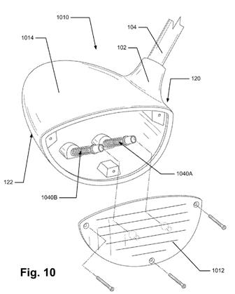
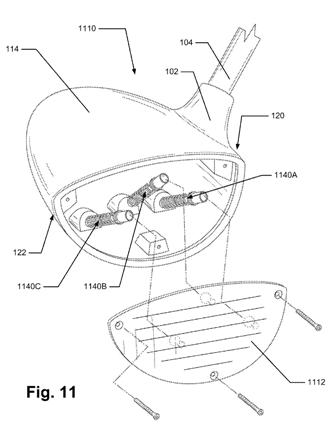
[0081] FIGS. 10 and 11 illustrate additional potential features of golf club heads 1010 1110 in accordance with at least some examples of this invention. These figures illustrate a brace system located at multiple different locations and/or different orientations with respect to a ball striking face 1012 1112 and a club head body 1014 1114. Generally, the brace system may include more than one brace as is illustrated in FIGS. 10 and 11. Additionally, the brace system may have different angular configurations in providing support to the ball striking face 1012 1112.
[0082] For example, as shown in FIG. 10, a first brace system 1040A may be located proximate the heel area 120 of the club head structure 1010 (to apply force at the heel area 120 of the ball striking face 1012), and a second brace system 1040B may be located in the toe area 122 of the club head structure 1010 (to apply force at the toe area 122 of the ball striking face 1012). If desired, braces inserted through any of the inlet ports may be sized, shaped, and adapted to extend to any of the desired face contact locations (e.g., so that a brace inserted at the toe end 122 contacts the middle or heel location 120 on the ball striking face 1012).
[0083] Another example golf club head 1110 in accordance with this invention, as shown in FIG. 11, includes a first brace system 1140A may be located in the heel area 120 of the club head structure 1110 (to apply force at the heel area 120 of the ball striking face 1112), a second brace system 1140B may be located in the central area of the club head structure 1110, between the heel area 120 and the toe area 122 (to apply force at the central area of the ball striking face 1112), and a third brace system 1140C may be located in the toe area 122 of the club head structure 1110 (to apply force at the toe area 122 of the ball striking face 1112). If desired, braces inserted through any of the inlet ports may be sized, shaped, and adapted to extend to any of the desired face contact locations (e.g., so that a brace inserted at the toe end 122 contacts the middle or heel location 120 on the ball striking face 1112).
[0084] An individual club head may have any one or more brace system orientations available, and the user or a club fitter can select which brace system orientation to use for a specific golfer, e.g., based on the contact pattern where the club head face tends to meet the ball. For example, using the club head as illustrated in FIG. 11, if the user predominantly makes contact at the toe end 122 of the ball striking face 1112, use of the heel oriented brace system 1140A may be most appropriate (e.g., to keep the toe end 122 more flexible but to maintain an overall COR response within the limitations of the rules). If the user predominantly makes contact at the heel end 120 of the ball striking face 1112, use of the toe oriented brace system 1140C may be most appropriate (e.g., to keep the heel end 120 more flexible but to maintain an overall COR response within the limitations of the rules). If the user has a very high swing speed or if his or her contact does not fall within a discernible, repeatable pattern, then use of the central brace system 1140B may be the most appropriate (e.g., to provide a backstop to prevent club damage and/or to maintain the ball striking face COR characteristics within the limitations of the rules). The various brace systems may include structure to receive the braces, e.g., in any of the various manners described above, and the various brace systems within a single club head (when multiple brace systems are present) may be the same or different without departing from this invention.
.
.
.
[0089] Additionally, in another embodiment in accordance with this invention, the golf club head may include an alternate bracing system to be included with the golf club heads as shown in FIGS. 2A through 5 and described above. The alternate bracing system may include an electronic/automatic adjustment mechanism in place of the manual adjustment on the ball striking face. The electronic/automatic adjustment mechanism may be a micro-electro-mechanical system (MEMS). The MEMS is operably connected to the ball striking face and may be part of bracing system to include the brace. A user can automatically adjust the bracing system via the MEMS to adjust the face angle and/or the loft angle of the ball striking face on a golf club head. Other adjustment systems may also be utilized such as systems using bi-stable structures as well as other mechanical or electro-mechanical structures.
[0090] The golf clubs and golf club heads as described herein provide many benefits and advantages over existing products. For example, the brace can be strategically located and designed to provide local stiffness and local flexibility in the ball striking face of the head so that certain areas of the ball striking face will have a COR response that is higher than other areas, without exceeding COR limits set by regulatory authorities. Golfers and club fitters can take advantage of aspects of this invention by having a user make multiple swings with a golf club and determining the area on the club head face where the golfer tends to make contact with the ball (e.g., using pressure sensitive contact tape). If an area of predominant contact is identified (e.g., the golfer tends to hit the ball in the toe area of the club), a head can be constructed so that the area of the ball striking face that most frequently impacts the ball during play will have a higher COR response. This can be accomplished by locating a contact area and providing a brace at the rear surface of the club head at a location away from the predominant contact area (at the heel area, in this example). A ball impacting these specific locations on the ball striking face (areas located away from the contact area and the brace) will have more energy and velocity transferred to it, thus resulting in longer hits.
[0091] An additional advantage of this invention relates to the ability to adjust the club head characteristics from golfer to golfer or even from shot to shot. As was described above, the club head includes a plurality of adjustment points which may be used to adjust the configuration of the ball striking face against the club body. The adjustment points may be adjusted to adjust the ball striking face in the up or down direction, thereby adjusting the loft angle of the club head. For example, golfers and club fitters can take advantage of this aspect of the invention by having a user make multiple swings with a golf club and determining the flight path of the ball after contact with the club head. If the golf ball consistently follows a boring or low shot pattern, the golfer or club fitter can increase the loft angle by adjusting the ball striking face up. Conversely, if the golf ball consistently follows a ballooning or high shot pattern, the golfer or club fitter can decrease the loft angle by adjusting the ball striking face down.
[0092] Additionally, the adjustment points may be adjusted to adjust the ball striking face in the left or right direction, thereby adjusting the face angle of the club head. For example, golfers, and club fitters can take advantage of this aspect of the invention by having a user make multiple swings with a golf club and determining the flight path of the ball after contact with the club head. In one example, the golfer consistently slices the ball because, due to a number of swing errors, the golfer delivers the club face to impact with the ball with the ball striking face open to the intended target. This swing causes the ball to slide, then roll, across the ball striking face from the heel toward the toe, which in turn causes the ball to leave the ball striking face with a slicing sidespin action. In accordance with example golf clubs of this invention, the golfer or club fitter can adjust the ball striking face to the left (for a right-handed golfer), thereby closing the ball striking face to the intended target. By changing the club head with a more closed face angle, the number of degrees that the golfer delivers the ball striking face open to impact with the ball is reduced, thereby reducing the slice sidespin imparted on the ball. In another example, the golfer consistently hooks the ball because, due to a number of swing errors, the golfer delivers the club face to impact with the ball with the ball striking face closed to the intended target. This hook swing causes the ball to slide, then roll, across the ball striking face from the toe toward the heel, which in turn causes the ball to leave the ball striking face with a hooking sidespin action. In accordance with example golf clubs of this invention, the golfer or club fitter adjust the ball striking face to the right (for a right-handed golfer), thereby opening the ball striking face to the intended target. By changing the club head with a more opened face angle, the number of degrees that the golfer delivers the ball striking face closed to impact with the ball is reduced, thereby reducing the hook sidespin imparted on the ball.
Any chance this design will ever make it to the market? Looks like a bunch of heavy components to me.
Dave Dawsey - Monitoring Adjustable Golf Club Inventions

Comments