Nike Golf’s New Tiger Ball? It Has Teeth
Corny title, but I couldn’t resist. Earlier this month I posted HERE about an unusual Nike Golf invention directed to an aerodynamic coating for a golf ball. It seems that there is no shortage of outside-the-box thinking going on at Nike R&D, as evidenced by a patent application that published today under the title “Golf Ball With Projections Adjacent Dimples.” Projections adjacent dimples, say what? The application describes the invention as:
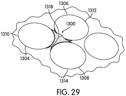
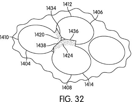
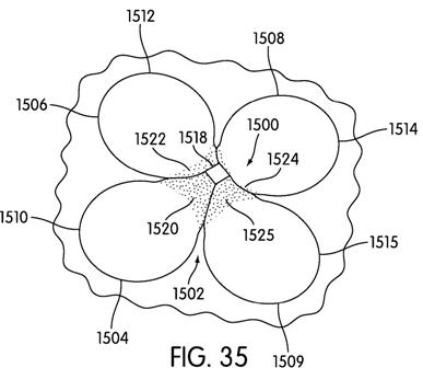
The application goes on to explain:
Those are some wild looking golf balls. I have to wonder if one of these balls hitting a green from 100 yards at 10,000 rpm would do any more damage than a typical ball (so, feel free to send me one and I will test it out).
David Dawsey – Keeping an Eye on Golf Ball Technology
PS – click HERE to read more interesting golf ball patent posts
A golf ball includes a projection that is positioned on a land adjacent two or more abutting dimples. The projection is located in a center or at a vertex of a shaped region defined by a pattern of dimples. A method for selecting a position for a projection and desirable configurations of the projection are also disclosed.


The application goes on to explain:
BACKGROUND
[0002] A typical ball 10 appears in FIG. 1. A typical ball has various characteristics. The ball has a particular weight, diameter, density, and dimple pattern. Striking a dimpled ball tends to create an improved flight path over striking a ball with no surface irregularities.
[0003] Golf balls are subject to two sets of rules. The first is the rules of the organization under whose rules the game is to be played. In many cases, that is the United States Golf Association (USGA). The USGA sets forth the limitations on golf balls to ensure that balls conform to certain standards to permit fairness among golfers. The USGA also certifies balls as meeting their rules.
[0004] There are a variety of rules a ball must follow under the USGA. For instance, the USGA has established rules regarding maximum weight, minimum size, and spherical symmetry. The maximum ball weight is 1.62 oz (45.93 g) and the minimum diameter is 1.68 inches (42.672) in diameter. The ball must be designed to be spherically symmetrical. These rules are updated every year, but the basic rules tend to remain the same.
[0005] The ball is also limited by the basic rules of physics. For example, balls fly differently based on the number, pattern, shape, and size of the dimples on the ball. Because many of the other variable features of the ball are regulated by the USGA, modifying the dimple patterns is a strategy used to improve the flight performance of the ball.
[0006] Modification of the size, number, and depth of the dimples can change the performance of a ball. On average, deep dimples on a ball tend to increase lift. Shallow dimples also allow the ball to have a higher trajectory and often create a longer flight time. Deep dimples allow the ball to have a lower trajectory an often create a longer run distance. This tends to create greater control, particularly in poor weather conditions. Increasing the number of dimples tends to create a straighter flight for the ball, but there is not a great deal of variation among balls that have between 300 and 500 dimples.
[0007] In addition to modifying the size and depth of the dimples, a ball will often have dimples that are arranged into a particular pattern. Common dimple patterns are the icosahedral and the dodecahedral. The icosahedral pattern is based on a polyhedron with twenty identical triangular faces, much like a twenty-sided die. Similarly, a dodecahedral is based on a polyhedron with twelve identical faces in the shape of pentagons. In addition, FIG. 2 shows a ball 20 that includes a dodecahedral pattern of multiple pentagons 22 on the surface of the ball 20. In addition to these patterns, other balls use other patterns that include multiple faces of varying polygonal and round shapes. Some balls include a pattern of dimples in a single shape and other balls include a pattern of dimples in a plurality of shapes.
[0008] Due to many factors, such as the limitations of the USGA rules and the materials from which balls are made, the ability to modify dimple size too greatly is limited. It is desirable that new and nonobvious structures that modify dimple size be developed.
.
.
.
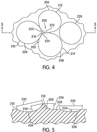
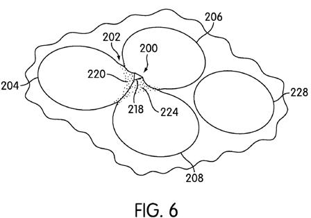
[0055] Turning now to FIGS. 4-6, a first embodiment of a projection or projecting finger 200 is shown. The projection 200 is positioned on a land section 202. Three dimples, specifically first dimple 204, second dimple 206, and third dimple 208, are adjacent one another and abut the land section 202. As shown most clearly in FIG. 5, the projection 200 extends continuously or as a continuous surface from first edge or rim 210 of first dimple 204 to an upper surface 218. While not detailed in cross sectional views, the projection also extends continuously from the second edge 212 of second abutting dimple 206 and third edge 214 of third abutting dimple 208. The stippling in FIGS. 4 and 6 on first side 220, second side 222, and third side 224 of the projection 200 is provided as a visual aid to more clearly see the side of the projection, but does not represent a discontinuity or any additional surface feature or any additional surface feature. Each of the first side 220, second side 222, and third side 224 extends laterally at least a portion of the circumference or rim of a corresponding first dimple 204, second dimple 206, and third dimple 208. Each of the first side 220, second side 222, and third side 224 extends upwardly to an upper surface 218. The upper surface 218 of the projection 200 is positioned above the level of the land 202 by a height 226. An appropriate height 226 may be selected based on a variety of factors, including, for example, the desire for a particular air flow around the projection, the choice of materials to be used in creating the ball, a desired ball density, or any other factors that a designer deems important or desirable. In some instances, the height 226 may be between about 0.1 mm and about 1 mm. The surface area of the upper surface 218 may also be selected based on similar considerations, but may be less than about 1.5 square millimeters.
[0056] Among the reasons a projection 200 of a particular height may be desirable is that the use of a projection 200 may increase the effective diameter and depth of a particular dimple. FIG. 5 shows the change in the effective diameter and depth between a non-abutting dimple 228 and an abutting dimple 202. The non-abutting dimple 228 has a diameter 230. The abutting dimple 202 has an effective diameter 232, which is greater than the diameter 230. The non-abutting dimple 228 has a depth 234. The abutting dimple 202 has an effective depth 236, which is greater than the depth 234. These changes in shape, size, and depth may affect the air flow around the projection and the ball as a whole and may create a different flight path for the ball than that created by a ball having no projections.
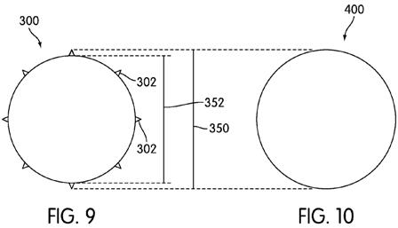
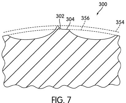
[0057] The use of projections in a plurality of locations around a ball may also affect the volume of the ball, as is shown in FIGS. 7-10. FIGS. 7 and 9 show cross sections of a ball 300 that includes projections 302. FIGS. 8 and 10 show cross sections of a ball 400 that is conventional and does not include projections. Turning first to FIGS. 9 and 10, it may be observed that the diameter 350 of the balls 300, 400 is the same. While a golf ball may have any diameter, it may be useful to make a golf ball that is at least as big as any minimum size requirements of the USGA or other certifying agency. If a ball 300 with projections 302 is used, the diameter 352 of the ball 300 at the level of lands 304 on the ball 300 is smaller than the diameter 350 at the level of the projections 302 and at the level of the lands 404 on the ball 400. This may also be observed in FIGS. 7 and 8. A circle 354 having a diameter 350 may be circumscribed around each ball 300, 400. A circle 356 having a diameter 352 may also be circumscribed around each ball 300, 400. The difference in diameters at the level of the lands 304, 404 indicates that while the two balls have the same total diameter 350, the volume of material in the ball 300 will be less than the volume of material in the ball 400. If the two balls 300, 400 have the same weight, such as the maximum permitted weight under a set of rules, the ball 300 can have a greater density. This greater density also changes the flight path of the ball. Thus, the use of the projections 302 on the ball 300 is likely to have a variety of effects on the path of the ball 300 when compared with the path of the ball 400. The use of the projections 302 may also allow the ball to be modified in other ways to achieve different performance characteristics. For example, the use of the projections may allow for the use of a different overall dimple configuration, a different ball density, or a different material to be used to create a different set of features for the ball.
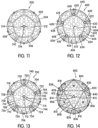
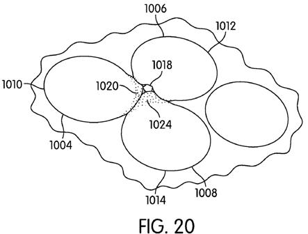
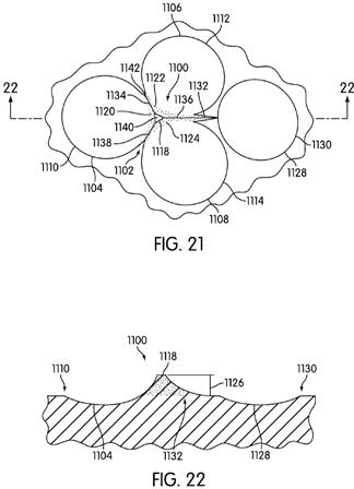
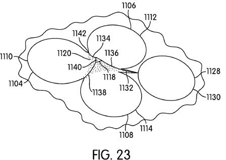
[0058] FIGS. 11-14 are included to show a variety of locations on a ball on which a projection may be placed. While any of the projections disclosed in this disclosure may be placed in a variety of locations around the ball, it may be useful to correlate the position of the projections with the dimple patterns on the ball. While certain locations are noted as being desirable, a person having ordinary skill in the art will be able to select an appropriate location for an appropriate projection based on the flight path characteristics and other features the designer things are desirable. The locations specifically disclosed are merely exemplary. In FIGS. 11-14, desirable locations of the projections are shown as circular areas with stippling. The use of the circular areas and stippling is to show the location more clearly on the ball, rather than to indicate any particular shape or texture.
Those are some wild looking golf balls. I have to wonder if one of these balls hitting a green from 100 yards at 10,000 rpm would do any more damage than a typical ball (so, feel free to send me one and I will test it out).
David Dawsey – Keeping an Eye on Golf Ball Technology
PS – click HERE to read more interesting golf ball patent posts

Comments