Compressible Grooves; Say What?
Yes, Nike Golf recently had a patent application publish under the title “Golf Club with Golf Club Head Having Compressible V-Shaped Grooves,” namely US Pub. No. 20100298062. This application will make you scratch your head and wonder…. genius? ridiculous? could this actually work?....
Dave Dawsey - Monitoring Golf Technology
PS – Check out other golf iron invention posts HERE
A golf club with a golf club head having compressible v-shaped grooves is presented. The club head may include a plurality of grooves formed in a striking face. In some arrangements, the grooves have a rectangular cross section. The grooves may also include a compressible insert having a v-shaped end and being formed of a material softer than that of the grooves. As the club head strikes a golf ball, the insert may compress, thereby allowing additional contact between the groove and the ball to impart spin on the ball. In an alternate arrangement, the groove may include a compressible support arranged between the insert and an end of the groove. The compressible insert may be formed of a material softer than the groove and/or the insert and is configured to compress when the club head strikes a golf ball.The application goes on to explain:
[0018] 1. Example Golf Clubs Having Compressible V-Shaped GroovesSounds like a cool new groove technology, but I can’t help but wonder what the USGA would have to say about it. Additionally, call me a natural skeptic, but I would have to see a high speed close-up video of an actual impact to really buy into the performance of this invention.
[0019] Aspects of this invention relate to golf club and golf club head structures. In at least some examples, the golf club head includes a plurality of grooves formed therein. In some arrangements, the grooves may have a rectangular cross section and may have an open end that corresponds to the striking face of the golf club head. In some examples, the grooves may include an insert shaped to correspond to the shape of the groove. The insert may include a v-shaped end corresponding to the open end of the groove and forming a portion of the striking face of the club.
[0020] In some examples, the groove may be formed of the same material as the face of the golf club head. This material may be a dense material, such as metal, composite, and the like. The insert may be formed of a softer material, i.e., a material having a softer durometer than the metal of the face and grooves, and may be configured to compress when the club head strikes a golf ball. In some examples, the insert will compress to a greater degree than the grooves. Compression of the insert increases contact between the grooves and the ball, thereby providing spin similar to that of a u-shaped groove. In some examples, the grooves may surround the inserts on three sides and may be in contact with the inserts on three sides.
[0021] In still other examples, the grooves may include a compression support arranged between the insert and the groove. The compression support may be formed of a less dense, softer material, i.e., a material having a softer durometer than that of the groove, and is configured to compress when the golf club strikes a golf ball. In some arrangements, the insert may be formed of the same or similar material to the groove. Alternatively, the insert may also be formed of a softer material than that of the groove.
[0022] Additional aspects and specific examples of the articles described above will be described in detail more fully below. The reader should understand that these specific examples are set forth merely to illustrate examples of the invention, and they should not be construed as limiting the invention.
[0023] B. Specific Examples of the Invention
.
.
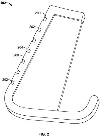
.[0032] With reference to FIG. 2, the golf club head 102 of FIG. 1 further includes a plurality of grooves 200 formed therein. The grooves 200 may be formed during the initial fabrication of the club head 102 (i.e., molded into the face 102a) or may be cut in after the manufacture of the face. In some arrangements, the grooves 200 may have a depth of 0.010 to 0.020 inches and a width of 0.020 to 0.035 inches. In addition, the plurality of grooves 200 may have a generally square or rectangular cross section. That is, when the grooves 200 are formed in the club head 102, the grooves 200 may have a generally square or rectangular cross section, however, one end may be exposed or open. In addition, the grooves 200 may include an insert 202 or filler portion that may be contained within each of the grooves 200. The insert 202 may have a generally square or rectangular cross section to correspond to the associated groove 200. The insert 202 may also have a generally v-shaped side 204 that is exposed. Generally speaking, the groove 200 formed in the face of the club 100 may surround the insert 202 on three sides and the insert 202 may have a v-shaped side 204 that forms a portion of the striking face of the club head 102.
[0033] In some arrangements, the grooves 200 may be integrally formed with the club head 102 or face 102a. That is, the grooves 200 and face 102a may be formed of the same material. In some arrangements, that material may be a metal, such as carbon steel, stainless steel, titanium (AO), etc., any type of hard coating (such as chrome or NANO), composite, and the like. Materials may be selected to make the grooves 200 sharp and durable. The material forming the grooves 200 may be a dense material to provide a sound striking surface for the club head 102.
[0034] Further, the golf club groove insert 202 may be formed of a material that is less dense than the material forming the surrounding grooves 200. For instance, the insert 202 may be formed of a soft durometer material, such as a polymer or thermal plastic, a metal softer than the metal used to form the surrounding grooves 200, etc., that may be configured to compress when the club head 102 strikes a ball, as will be discussed more fully below.
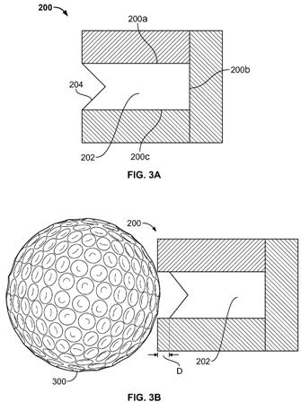
[0035] For example, FIGS. 3A and 3B illustrate one example groove 200 with v-shaped insert 202. The figures depict one enlarged groove 200 to illustrate compression of the insert 202. FIG. 3A illustrates a cross section of one groove 200 according to aspects described herein. The groove 200 has a generally rectangular cross section with three sides 200a-200c and one exposed end. The groove 200 may formed of a dense material, as described above. The insert 202 is generally surrounded by the groove 200 on three sides and, in some arrangements, may be in contact with the groove 200 on three sides. The insert 202 may be formed of a less dense or softer material than the groove material, as described above to permit compression of the insert 202 when the club head strikes a golf ball. The insert 202 may also include a v-shaped end 204 corresponding to the exposed end of the groove 200. The v-shaped end 204 of the insert 202 may form a portion of the striking face of the club head.
[0036] FIG. 3B illustrates one golf ball striking arrangement of the groove 200 and insert 202 shown in FIG. 3A. FIG. 3B also includes a golf ball 300, however, the scale of the ball 300 has been altered to more clearly illustrate compression of the insert 202. As the club face and plurality of grooves 200 strike the ball 300, the dense material forming the groove 200 may compress slightly. However, the insert 202, formed of a softer durometer material than the groove 200 itself, will compress a distance, D, as shown in FIG. 3B. Due to the softer nature of the insert material than the groove material, the insert 202 will compress to a greater extent than the groove 200. This compression of the insert 202 may cause the generally v-shaped insert 202 shown to exhibit behavior, performance characteristics, etc. of a u-shaped groove. For instance, as the insert 202 compresses, the adjacent denser metal of the groove 200 contacts the golf ball 300, thereby adding spin similar to a u-shaped groove. The spin imparted may be affected by the lie condition, loft of the club, and/or angle of attack.
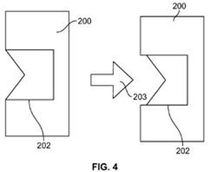
[0037] FIG. 4 illustrates this compression in an isolated view without the golf ball 300. The figure on the left illustrates one example groove 200 in a non-compressed, at-rest position. That is, the groove 200 may be formed in a club or club face that is not in contact with a golf ball. The figure on the right illustrates compression of the insert 202 when the club head, and therefore the groove 200 and insert 202, contact a golf ball. Arrow 203 indicates the force on the club face, groove 200 and insert 202 as the club head strikes a ball. As shown, the insert 202 may compress more than the groove 200, allowing contact between the metal of the groove 200 and the ball which will add spin similar to a u-shaped groove, as described above.
Dave Dawsey - Monitoring Golf Technology
PS – Check out other golf iron invention posts HERE


Comments