A Wild New PING Dynamically Variable MOI Driver
The Golf-Patents blog has revealed some pretty radical golf club designs in the past, but rarely do they originate from Karsten Manufacturing (aka PING). Therefore, when an unusual PING patent application is published it deserves a close look. This week PING had two related patent applications publish related to variable MOI driver designs, one of which is US Pub. No. 20100029402 titled “Golf Clubs With Variable Moment of Inertia And Methods Of Manufacture Thereof.” The application explains:
Wow, I suspect that design concept will surprise a lot of people; but will it ever make it to the market?
Dave Dawsey - Monitoring Golf Technology Inventions
[0002] Some individuals who play golf may have a tendency to hit a golf ball with a hook or draw, or a slide or facie. These unintended trajectories can be the result of hitting the golf ball outside a central region of the golf club face. Hitting the golf ball outside this region can rotate the golf club head, which can cause an unintended spin on the golf ball, and this spin can exacerbate an individual's tendency to hook/draw or slide/fade the golf ball. Therefore, a need exists to minimize the club head rotation when an individual hits a golf ball outside the central region of the golf club face.
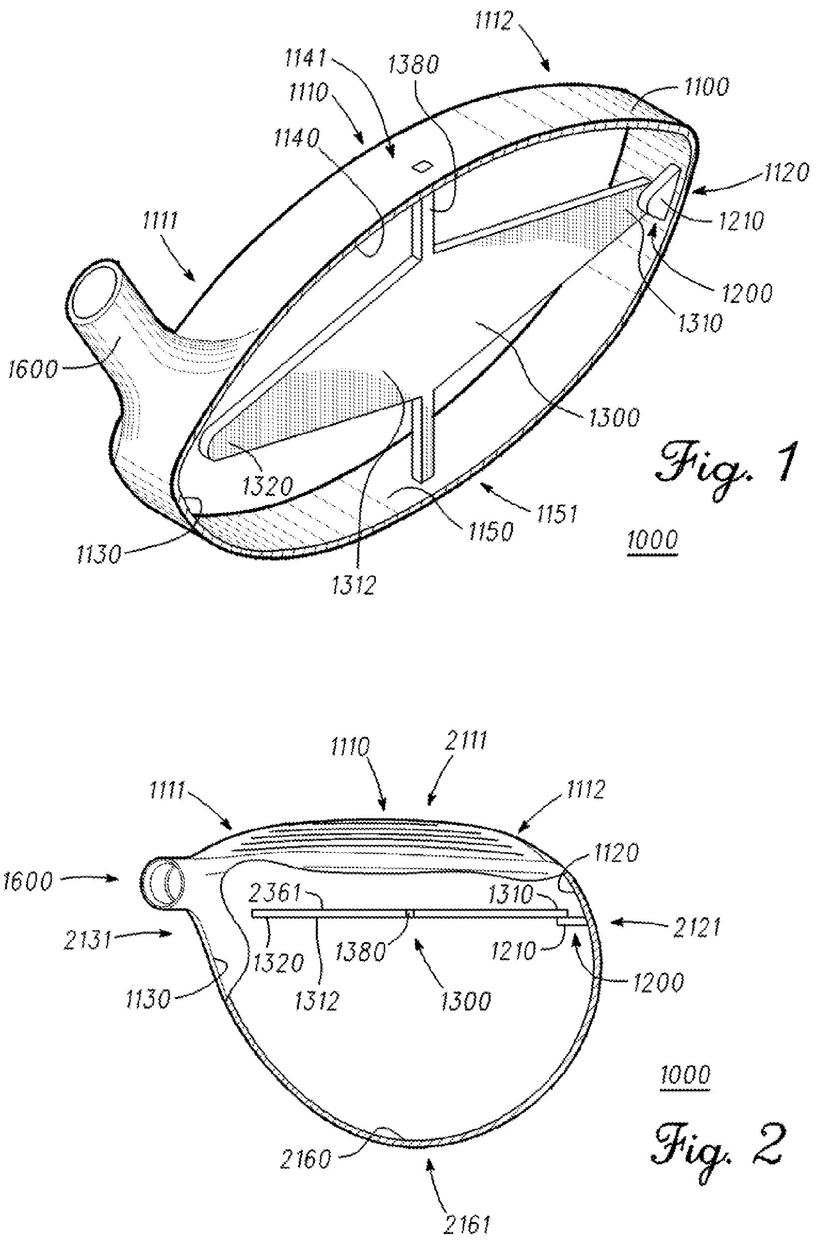
[0065] As illustrated in FIGS. 1-4, golf club head 1000 comprises a body 1100 having a front section 1110, a restrictor mechanism 1200, and a weight 1300. In some embodiments, front section 1110 can be referred to as a face, or can comprise a face of golf club head 1000. In the same or different embodiments, body 1100 can be referred to as a housing. In the same or a different embodiment, body 1100 can comprise at least one of a steel material, a titanium material, an aluminum material, a graphite material, and/or other suitable materials. Golf club head 1000 can form part of a golf club with a golf club shaft (not shown) coupled to a hosel 1600 and/or a bore of golf club head 1000.
[0066] Restrictor mechanism 1200 of golf club head 1000 comprises restrictor 1210, and is coupled to body portion 1120 of body 1100. Body 1100 can also be subdivided into other portions, such as body portions 1130, 1140, 1150, and/or 2160 (FIG. 2). In the same or a different embodiment, front section 1110 can be at or proximate to a front 2111 of golf club head 1000, body portion 1120 can be at or proximate to a toe 2121 of golf club head 1000, body portion 1130 can be at or proximate to a heel 2131 of golf club head 1000, body portion 1140 can be at or proximate to a top 1141 of golf club head 1000, body portion 1150 can be at or proximate to a bottom 1151 of golf club head 1000, and/or body portion 2160 can be at or proximate to a back 2161 of golf club head 1000. Some embodiments may refer to body portions 1120, 1130, 1140, 1150, and/or 1160 as sections.
[0067] Weight 1300 is coupled to body 1100 and comprises weight end 1310 coupled to restrictor mechanism 1200. In the present embodiment, weight 1300 also comprises weight end 1320. Restrictor 1210 comprises a stiffness correlated with a Young's modulus of a material from which restrictor 1210 is made. In one example, restrictor 1210 comprises at least one of a steel material, a titanium material, an aluminum material, and/or any other suitable materials. In the same or a different embodiment, weight 1300 can comprise a mass of approximately 20 to 40 grams. In the same or a different embodiment, weight 1300 can comprise approximately 10 to 20 percent of a mass of golf club head 1000. In some embodiments, weight 1300 can comprise at least one of a tungsten material, a tungsten-epoxy material, a steel material, a copper material, a titanium material, and/or a bronze material.
[0068] As shown in FIGS. 1-2, weight 1300 of golf club head 1000 further comprises post 1380. In the present embodiment, post 1380 is coupled to body portions 1140 and 1150 of body 1100. In some embodiments, post 1380 can also be referred to as a restrictor, and can comprise a stiffness which can be less than a stiffness of restrictor 1210. Weight 1300 is at least as stiff as restrictor 1210 and can be stiffer than post 1380.
[0069] Post 1380 is configured to couple weight 1300 to body 1100, and to align weight end 1310 with restrictor 1210. In turn, restrictor 1210 is positioned behind end 1310 of weight 1300 relative to front section 1110 of body 1100 in the present embodiment. In addition, face 2361 (FIG. 2) of weight 1300 is aligned substantially parallel to front section 1110 of body 1100.
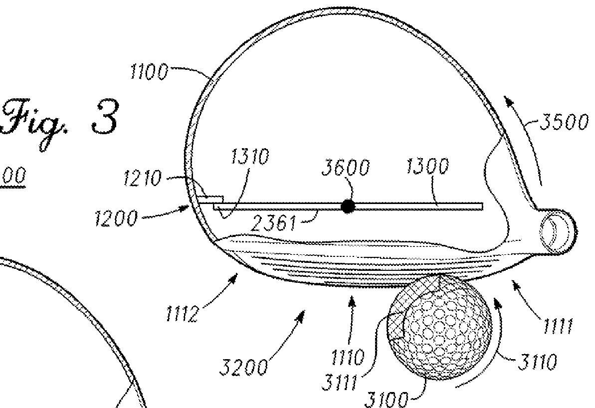
[0070] As shown in FIGS. 3-4 for the present embodiment, center of gravity 3600 of weight 1300 can be proximate to front section 1110 of golf club head 1000. In the same or a different example, center of gravity 3600 of weight 1300 can be proximate to a center of gravity of golf club head 1000. In a different example, center of gravity 3600 of weight 1300 can be proximate to a geometric center of golf club head 1000. In the same or a different example, center of gravity 3600 is substantially collinear with a gravitational vector through the center of gravity of golf club head 1000.
[0071] As shown in FIG. 3, the stiffness of restrictor 1210 is configured to resist a deformation of restrictor 1210 by end 1310 of weight 1300 in response to an impact at zone 1111 of body 1100. Restrictor mechanism 1200 can thus interact with weight end 1310 by resisting deformation of restrictor 1210 due to its stiffness. In other embodiments, the stiffness can be configured to permit certain deformation of restrictor 1210 to interact with weight end 1310. In the same or a different embodiment, deformation of restrictor 1210 can be elastic but restrictor 1210 may return to its original shape after deformation. In some embodiments, a deformation of a restrictor such as restrictor 1210 can be referred to as a distortion.
[0072] In the present example of FIG. 3, face 3200 of golf club head 1000 impacts ball 3100 substantially square with respect to an intended direction of travel for golf ball 3100. The impact at zone 1111 is proximate to the heel of golf club head 1000 in this example, thus imparting a counterclockwise rotation upon golf club head 1000, as denoted by arrow 3500. In the current embodiment, and for simplicity of description and illustration, the counterclockwise rotation is about center of gravity 3600. In other embodiments, golf club head 1000 can rotate about a different point.
[0073] Continuing with the example of FIG. 3, the counterclockwise rotation of golf club head 1000 causes restrictor 1210 to also rotate counterclockwise along with body 1100 and, as a result, to interact with end 1310 of weight 1300. As restrictor 1210 is pressed against weight end 1310, restrictor 1210 resists deformation due to its stiffness. As a result, the moment of inertia of weight 1300 is transferred through restrictor 1210 onto body 1100. In some embodiments, restrictor 1210 also impedes a rotational tendency of weight 1300 relative to body 1100 when golf club head 1000 rotates counterclockwise in response to impact with golf ball 3100. Golf club head 1000 therefore exhibits a higher moment of inertia when weight 1300 interacts with restrictor 1210, decreasing the amount of corresponding rotation 3500 imparted onto golf club head 1000 upon impact with golf ball 3100.[0094] Continuing with the figures, FIG. 15 illustrates a perspective cross-sectional view of part of golf club head 15000 comprising one dual-restrictor mechanism FIG. 16 illustrates a top cross-sectional view of golf club bead 15000. Golf club head 15000 is similar to golf club head 1000, but comprises restrictor mechanism 15200 rather than 1200. Restrictor mechanism 15200 comprises restrictor 1210 similar to as described above for restrictor mechanism 1200 in FIGS. 1-2. However, restrictor mechanisms 15200 and 1200 (FIG. 1-2) differ in that restrictor mechanism 15200 is a dual-restrictor mechanism that further comprises restrictor 15220 located at an opposite side of weight 1300 than restrictor 1210. In addition, weight end 1310 of weight 1300 is configured to be positioned between restrictors 1210 and 15220. In the same or a different embodiment, weight end 1310 is within body 1100.
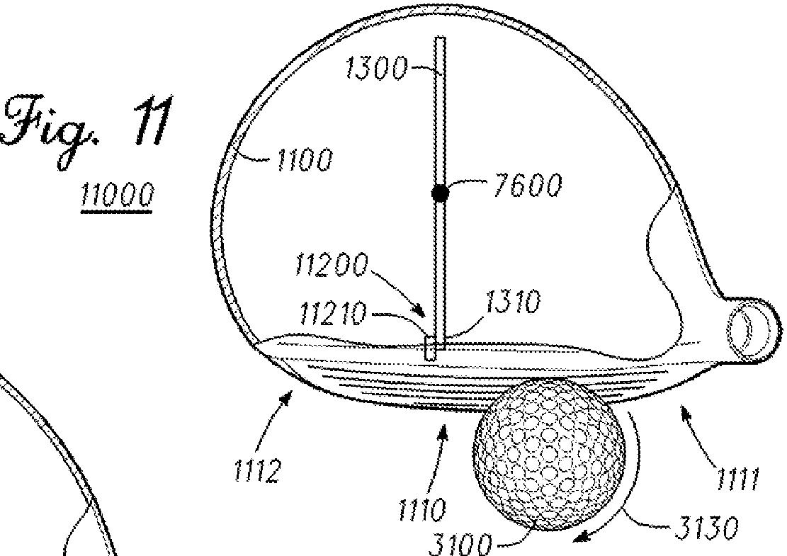
[0092] FIGS. 11-14 illustrate embodiments where a face of weight 1300 is aligned substantially perpendicular to front section 1110 of body 1100 of golf club head 7000. Restrictor mechanisms 11200 and 13200 are accordingly positioned proximate to front section 1110 to align with weight end 1310. In a different embodiment, restrictor mechanisms 11200 and 13200 can be positioned proximate to a rear of the golf club heads, opposite front section 1110.
[0093] Despite the different alignments, the embodiments in FIGS. 11-14 can perform in a manner similar to the embodiments in FIGS. 7-10, respectively, upon impact with golf bail 3100. For example, the situations shown in FIGS. 11 and 13 are likely to generate an interaction between weight end 1310 and restrictors 11210 and 13210, respectively, similar to as previously described for the analogous situations shown in FIGS. 7 and 9. Similarly, the situations shown in FIGS. 12 and 14 are less likely to generate an interaction between weight end 1310 and restrictors 11210 and 13210, respectively, similar to as previously described for the analogous situations shown in FIGS. 5 and 10.
[0095] In the present embodiment of FIGS. 15-16, restrictor 15220 comprises a stiffness, where the stiffness of restrictor 1210 is greater than the stiffness of restrictor 15220. Here, the stiffness of restrictor 15220 is configured to permit a deformation of restrictor 15220 by weight end 1310 in response to an impact at zone 1112 of body 1100 of golf club head 15000. The impact at zone 1112 could be, for example, with golf ball 3100. In the same or a different embodiment, restrictor 15220 can comprise at least one of a silicon material, a polymer material, and an epoxy material. In a different embodiment, the relative stiffnesses of restrictors 1210 and 15220 could be inverted, such that stiffness 15221 could be greater than stiffness 1211. In the same or a different embodiment, weight end 1310 can be connected to at least one of restrictors 1210 and 15220, such as by welding, bonding, soldering, and/or gluing, among other techniques.
[0096] In the example of FIGS. 15-1.6, when golf club head 15000 rotates counterclockwise upon an impact at zone 1111, restrictor 1210 tends to interact with weight end 1310. Because the stiffness of restrictor 1210 is greater than the stiffness of restrictor 15220, restrictor 1210 tends to resist deformation due to the interaction, and thus may transfer a comparatively greater moment of inertia from weight 1300 to body 1100 of golf club head 15000. Conversely, when golf club head 15000 rotates clockwise upon an impact at zone 1112, restrictor 15220 may interact with weight end 1310. Because the stiffness of restrictor 15220 is less than the stiffness of restrictor 1210 in this example, restrictor 15220 tends to deform and/or compress due to the interaction, and thus may transfer a comparatively lesser moment of inertia from weight 1300 to body 1100 of golf club head 15000.
Dave Dawsey - Monitoring Golf Technology Inventions


Comments