Pull This Putting Invention Out on the Practice Green and You May Get a Few Stares
I love inventions directed to conquering this maddening sport. It is a sign that human spirit is alive and well; and that some tinkerers truly believe they have invented a gadget that will make the game less frustrating for the rest of us.
Sure, there are those golfers (typically the ones that throw their clubs and angrily smack their ball of the green after missing a short putt) that bash every new golf product created since the advent of laminated woods; but can you really knock a golf training product until you have tried it out? OK, I suppose there are a few (example 1, example 2, example 3) that I do draw quick conclusions about, but in general I would be willing to try any training product that the inventor really believes will help a golfer enjoy the game (provided it doesn’t look like it could inflict bodily harm). Thus, I come upon the following putting training aid invention with an open mind. Check this out.


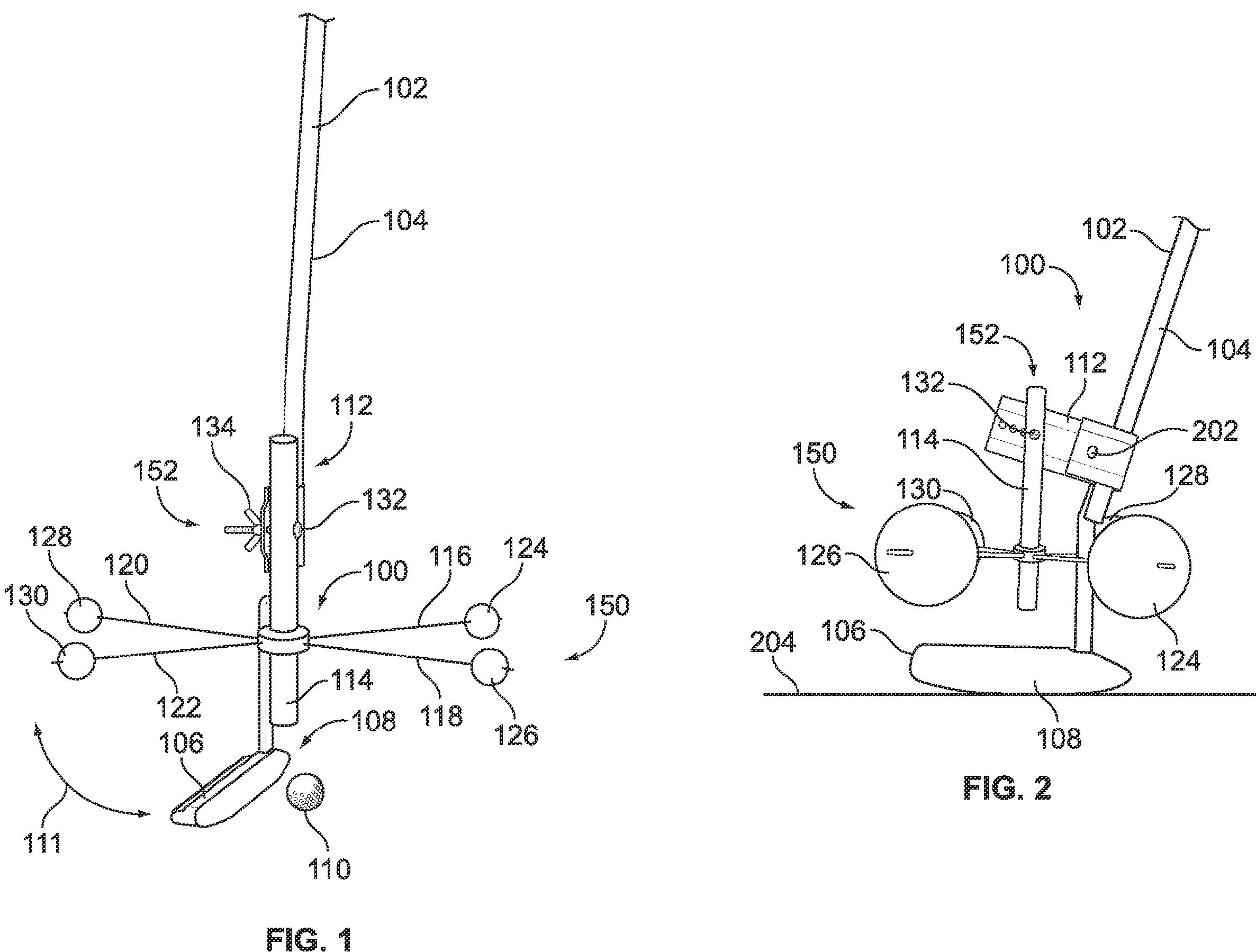
The drawings come from a patent application that was published today as US Pub. No. 20100016093 titled “Golf Putter Training Device.” The application explains the invention as:
It reminds me of an anemometer, however apparently the ping-pong balls don’t spin. Oh well, it doesn’t look like it could screw up a putting stroke, so sign me up. I would give it a try.
Dave Dawsey - Watching Golf Putting Patents
PS – check out additional putter patents HERE
Sure, there are those golfers (typically the ones that throw their clubs and angrily smack their ball of the green after missing a short putt) that bash every new golf product created since the advent of laminated woods; but can you really knock a golf training product until you have tried it out? OK, I suppose there are a few (example 1, example 2, example 3) that I do draw quick conclusions about, but in general I would be willing to try any training product that the inventor really believes will help a golfer enjoy the game (provided it doesn’t look like it could inflict bodily harm). Thus, I come upon the following putting training aid invention with an open mind. Check this out.


The drawings come from a patent application that was published today as US Pub. No. 20100016093 titled “Golf Putter Training Device.” The application explains the invention as:
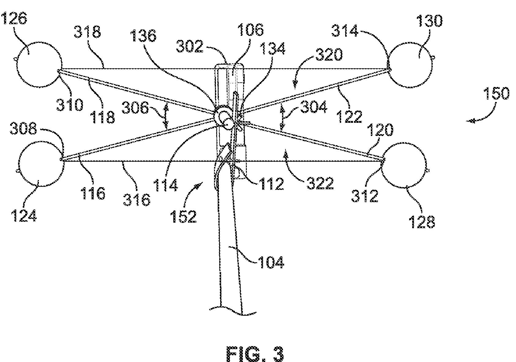
[0019] Turning now to FIG. 3, the support shaft 114 is positioned directly over the putting head 106. Additionally, support shaft 114 is positioned over the portion of the putting head 106 that a golfer would be desire to have make contact with a ball 110 during a putt. For example, support shaft 114 may be equidistant from the end 302 of the putting head 106 and where the shaft 104 is attached to the putting head 106. It is understood, however, that support shaft 114 may be positioned in any suitable location with respect to putting head 106, whether over putting head (from a top view) or not. Furthermore, in one example, support shaft 114 is perpendicular to the ground when the golfer is lining a golf putter 102 up for a putt. More specifically, when putting head 106 is substantially parallel to the ground 204 as shown in FIG. 2, the support shaft 114 is substantially perpendicular to both the putting head 106 and the ground 204. As one skilled in the art will recognize, however, various orientations and positions of mounting bracket 112 and support shaft 114 may be better suited for particular training exercises for enhancing one's golf putting skills.
[0020] Turning back to FIG. 3, visual guide assembly 150 comprising visual guides 116, 118, 120, and 122, is shown from a top view. Visual guide assembly 150 may also include a first outer visual guide 316 and a second outer visual guide 318, as described below. Visual guides 116 through 122 are connected to support shaft 114. In this example, a mounting ring 136 is adapted to receive support shaft 114. It is understood, however, that visual guides 116, 118, 120, and 122 may be directly mounted to support shaft 114. It is further understood, as described above, that the entire golf putter training device 100 may be made from one material and perhaps even one piece. For example, FIG. 5 shows a one-piece embodiment of visual guide assembly 450, as will later be described.
[0021] Visual guides 116, 118, 120, and 122 are preferably formed from a lightweight material, such as fiberglass or lightweight plastic or other similar material. When mounted to mounting ring 136, visual guides 116, 118, 120, and 122 are preferably substantially parallel to ground 204 when support shaft 114 is perpendicular thereto. Furthermore, angle 304 and angle 306 are preferably about 300. However, it is understood that angles 304 and 306 may be any desired angle that may be used to help improve one's golf putting skills. Furthermore, angles 304 and 306 may not be equal. Additionally, it is understood that visual guides 116, 118, 120, and 122 need not be substantially parallel to ground 204. Visual guide assembly 150 may also include a first outer visual guide 316 and a second outer visual guide 318, as described below.
[0022] Visual guides 116, 118, 120, and 122 provide multiple forms of visual feedback to the golfer to help the golfer develop muscle memory of a good putting technique. For example, one problem that golfers have while putting is an unsteady swing. It is preferred that a golf putting swing be relatively smooth. Because of the extended length of visual aids 116, 118, 120, and 122, visual aids 116, 118, 120, and 122 have a tendency to show movement during an unsteady swing. Although unsteadiness may be seen by a careful observer watching putting head 106, the unsteadiness may be very difficult to see. Visual aids 116, 118, 120, and 122, however, amplify every movement that a putting head 106 makes during a swing. Not only will the golfer be able to have immediate feedback from the visual guides 116 through 122, an observer, such as a golf instructor, will better be able to perceive any undesired rotation or movement of a putting head 106 during a golf putter swing.
[0023] To further enhance the ability to observe and detect any undesired characteristics of a golf putter swing, golf putter training device 100 also includes one or more visual indicators. As shown in FIGS. 1 through 4, visual indicators 124, 126, 128, 130 are connected to an end 308, 310, 312, and 314 of visual guides 116 through 122, respectively. More specifically, visual indicator 124 is connected to end 308 of visual guide 116; visual indicator 126 is connected to end 310 of visual guide 118; visual indicator 128 is connected to end 312 of visual guide 120; and visual indicator 130 is connected to end 314 of visual guide 122. In one example, visual indicators 124 through 130 are table tennis balls, and each visual indicator 124 through 130 is connected to its respective visual guide 116 through 122 by inserting the ends of visual guides 116 through 122 through each of the table tennis balls. It is understood, however, that any suitable visual indicator 124 through 130 maybe used, such as a visual indicator made of plastic, cloth, metal, or any other suitable material or formed of another shape. For example, the alternative embodiment shown in FIG. 5, as will later be described, has visual indicators 424 through 430 formed in the shape of flat discs.
It reminds me of an anemometer, however apparently the ping-pong balls don’t spin. Oh well, it doesn’t look like it could screw up a putting stroke, so sign me up. I would give it a try.
Dave Dawsey - Watching Golf Putting Patents
PS – check out additional putter patents HERE

Comments