
What’s Next in Adjustability? Perhaps Adjustable Grooves by Nike Golf
Nike Golf had an interesting patent application publish this
week as US Pub. No. 20130017898 titled “Golf Clubs and Golf Club Heads Having
Adjustable Characteristics.” The application describes the invention as:
A golf club head which may include a golf club head body, a
ball striking face and a piezoelectric member in the golf club head, wherein
the piezoelectric member is configured to be selectively adjusted by an input
provided through a controller operably connected to the piezoelectric member.
Further, the piezoelectric member may be capable of having a first
configuration to provide the golf club head body with a first attribute and may
also be capable of having a second configuration to provide the body with a
second attribute in response to the input provided by the controller. Further,
the second attribute may be different from the first attribute.
It goes on to explain:
SUMMARY OF THE INVENTION
[0006] Aspects of the disclosure may relate to a golf club
head including a golf club head body, a ball striking face and a piezoelectric
member in the golf club head, wherein the piezoelectric member is configured to
be selectively adjusted by an input provided through a controller operably
connected to the piezoelectric member. Further, the piezoelectric member may be
capable of having a first configuration to provide the golf club head body with
a first attribute and may also be capable of having a second configuration to
provide the body with a second attribute in response to the input provided by
the controller. Further, the second attribute may be different from the first
attribute.[0007] Further, aspects of the disclosure may relate to a
golf club which may include a golf club head with a golf club head body, a ball
striking face and a piezoelectric member in the golf club head body. Further,
the golf club may include a shaft configured to be engaged with the golf club
head and a controller operably connected to the piezoelectric member.
Additionally, the controller may be configured to allow the user to selectively
adjust a configuration of the piezoelectric member by providing an input
through the controller. Also, the piezoelectric member may be capable of having
a first configuration to provide the golf club head body with a first attribute
and may also be capable of having a second configuration to provide the body
with a second attribute in response to the input provided by the controller,
the second attribute being different from the first attribute..
.
.
I. General Description of Example Golf Club Heads, Golf
Clubs, and Methods in Accordance with this Invention[0029] Aspects of this disclosure relate to iron-type golf club heads. Iron-type
golf club heads according to at least some example aspects of this disclosure
may include: (a) an iron-type golf club head body; (b) a ball striking face;
and (c) at least one piezoelectric element in the iron-type golf club head
body. According to aspects of this disclosure, the one or more piezoelectric
elements in the iron-type golf club head may be configured to selectively
adjust attributes, characteristics or properties of the iron-type golf club
head. For example, according to aspects of the disclosure, the size, shape,
positioning, etc. of the one or more piezoelectric elements in the iron-type
golf club head may be configured to selectively control various attributes of
the iron-type golf club head, including the configuration of the grooves in the
iron-type golf club head (e.g., the depth, volume, shape, angle, etc. of the
grooves), the stiffness or dampening ability of the iron-type golf club head,
the loft of the golf club head iron-type golf club head, etc..
.
.
[0042] According to aspects of the disclosure, the golf club
head 102 may include at least one piezoelectric member 120 associated
therewith. A piezoelectric member may include an element with piezoelectric
properties. It is noted that an element with piezoelectric properties may
generate an electrical voltage when a mechanical strain or stress is applied.
Further, conversely, the element with piezoelectric properties may deform
mechanically when an electric field is applied. For example, according to aspects
of the disclosure, an electric field may be applied to the piezoelectric member
120 which causes a change in the configuration (e.g., the size or dimensions)
of the piezoelectric member 120. For example, the size of the piezoelectric
member 120 may increase (e.g., “grow”) or decrease
(“shrink”) when an electric field is applied. Further, the size of
the piezoelectric member 120 may tend to return to their original shape when
the electric field is removed. Further, the amount the piezoelectric member 120
deforms (e.g., the amount the piezoelectric member 120 increases or decreases
in size) during the time the electric field is applied may be dependent upon
the strength of the electric field. For example, according to aspects of the
disclosure, the piezoelectric member 120 may deform by a first amount (e.g.,
increase or decrease by a first size) if a first voltage is applied and may
deform by a second, larger amount (e.g., increase or decrease by a second,
larger size) if a second larger voltage is applied.[0043] Therefore, according to aspects of the disclosure, one or more
piezoelectric members 120 may be used in a the golf club head 102 to control
and selectively alter various attributes, characteristics or properties of the
iron-type golf club head. For example, according to aspects of the disclosure,
one or more piezoelectric members 120 may be incorporated into the golf club
heads 102 and an electric field may be applied to the one or more piezoelectric
members 120 to selectively alter various attributes, characteristics or
properties of the iron-type golf club head. It is noted that according to
aspects of the disclosure, attributes may include mechanical or physical
properties of the golf club head. For example, the attributes may include the configuration
of the grooves in the iron-type golf club head (e.g., the depth, volume, shape,
angle, etc., of the grooves); the internal stress, stiffness or hardness behind
the ball striking face of the golf club head; the loft angle of the golf club
head; etc. Further, it is noted that attributes may affect the trajectory of
the golf ball after impact with the golf club head (e.g., by affecting how the
golf ball leaves off the ball striking face of the golf club head). For
example, the attributes may affect the trajectory of the golf ball after impact
with the golf club head by affecting the backspin of the golf ball, the lofted
flight of the golf ball, etc.
[0044] According to aspects of the disclosure any element with piezoelectric
properties may be used as the piezoelectric member 120. For example, according
to aspects of the disclosure, polymers having piezoelectric properties may be
used as the piezoelectric member 120. By way of example, polyvinylidine
diflouride (PVDF) is an element with piezoelectric properties that may be used
as the piezoelectric member 120 in accordance with aspects of the disclosure.
[0045] According to aspects of the disclosure, and as seen in FIG. 3, the golf
club head 100 may include a controller 122 for activating the piezoelectric
member 120 associated with the golf club head 120. For example, as shown in
FIG. 3, the shaft 107 may be configured to support the controller 122.
According to aspects of the disclosure, the controller 122 may be operably
connected to the piezoelectric member 120. For example, the controller 122 may
include wires which transmit the electric field (e.g., via an electric current)
from a power source (e.g., a battery) to the piezoelectric member 120. Other
various types of conductors can also be used.
[0046] According to aspects of the disclosure, the controller 122 may include a
switch, a knob, or dial, 124 which may be configured to rotate to control the
electric field applied to the piezoelectric material 120. For example, the knob
124 may be configured to be rotated from a first (e.g., “off”)
position, wherein no electric field is generated, to a second (e.g.,
“on”) position, wherein an electric field is generated and applied to
the piezoelectric material 120. According to aspects of the disclosure, upon
the electric field being generated and applied to the piezoelectric material
120, the size of the piezoelectric member 120 may be increased or decreased as
discussed above. Conversely, when the knob 124 is rotated back to the off
position and the electric field is removed, then as discussed above, the size
of the piezoelectric member 120 may decrease or increase back to its original
size.
[0047] Further, according to aspects of the disclosure, the controller 122 may
be configured to vary the strength of the electric field (e.g., the amount of
voltage) applied to the piezoelectric material 120. For example, according to
aspects of the disclosure, the knob 124 may be configured to rotate between
various positions, which, in turn, increase or decrease the strength of the
electric field. For example, one position to which the knob 124 may be rotated
may correspond to a voltage of 1.5V, a second position to which the knob 124
may be rotated may correspond to a voltage of 3.0V, etc. In this way, the golfer
may selectively adjust the size of the piezoelectric material 120 and, thereby,
selectively alter and control various attributes, characteristics or properties
of the iron-type golf club head. It is noted that the above voltages are merely
illustrative and other voltages may be applied as desired.
[0048] As seen in FIG. 3, the shaft 106 may include a compartment configured to
receive a battery or other power source. Further, according to aspects of the
disclosure, the controller 122 may be configured to be connected to the one or
more power source (e.g., through one or more of leads connected to the battery
or power source) in order to apply the electric field to the piezoelectric
material 120. According to aspects of the disclosure, a portion of the shaft
106 (e.g., the handle 107) may be removeably engaged with the remainder of the
shaft 106 (e.g., through threads or other mechanical connectors) in order to
allow access to the battery or power supply (e.g., to insert or replace the
battery or power supply).
[0049] According to aspects of the disclosure, the piezoelectric member 120 may
be activated by the hand or grip of the golfer when the golfer grips the golf
club 100. For example, according to aspects of the disclosure, the golf club
100 may include a button or switch (e.g., a button or switch positioned at or
near the handle 107) that is depressed or otherwise activated (e.g., a switch
activated by pressure) when the golf grips the golf club 100. By activating the
button, the electric field may be applied to the piezoelectric member 120
(e.g., through wires running through the shaft 106) to deform the piezoelectric
member 120 (e.g., to increase or decrease the size of the piezoelectric member
120). For example, when the button is depressed, a circuit may be completed
through which the electric field may be applied to the piezoelectric member
120. Further, it is noted that according to such an embodiment of the golf club
100, the knob 124 may be incorporated to modify the voltage applied to the piezoelectric
member 120 as described above.
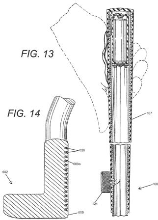
[0050] Alternatively, the golfer may wear a glove which could include an
external power source or other structure designed to complete a circuit to
activate the piezoelectric member. FIG. 13 shows a cross-sectional view of the
golf club 100 in which an illustrative embodiment such a controller 122 is
configured. As seen in FIG. 13, according to aspects of the disclosure, the
golf club 100 may include exposed portions (e.g., a switch, electrical lead,
etc. positioned at or near the handle 107). The glove may include a material
that will serve to complete a circuit that activates the piezoelectric member
120. For example, the glove may include a conducting material positioned on the
exterior of the palm of the glove. Thereby, when the golfer grips the handle,
the conducting material engages the exposed leads and completes the circuit
through which the electric field may be applied to the piezoelectric member
120. Conversely, the golfer releases the handle, the circuit is opened and,
consequently, the electric field may be removed from the piezoelectric member
120.
[0051] According to particular aspects of the disclosure, the glove may contain
the power source (e.g., a battery) instead of (or in addition to) the golf club
100. For example, the glove may contain a battery through which the electric
field may be applied to the piezoelectric member 120 when the golfer grips of
the handle and the conducting material engages the exposed leads and completes
the circuit. According to aspects of the disclosure, the battery may be in
contact with the leads in order to complete the circuit and apply the electric
field to the piezoelectric member 120. Alternatively, the battery may contact
wires or other conducting material positioned on the exterior of the glove,
which in turn contacts the leads in order to complete the circuit and apply the
electric field to the piezoelectric member 120.
[0052] FIGS. 4A, 4B, 4C, 5A and 5B show various views of the illustrative
embodiment of the golf club head 102 according to aspects of the disclosure.
According to aspects of the disclosure and as illustrated in the embodiment
shown in FIGS. 1, 3, 4A, 4B, 4C, 5A and 5B, piezoelectric material may be
configured within the golf club head 102 to control the depth of the grooves
109a of the golf club head 102. Hence, as will be discussed below, according to
aspects of the disclosure, the piezoelectric member 120 may be used to
selectively control and adjust the depth of the grooves of the golf club head
102 and, thereby, the amount of backspin imparted to the golf ball by the golf
club head 102 and also the launch angle and ball speed.
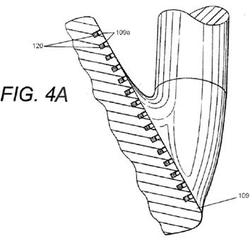
[0053] Specifically, FIG. 4A is a partial cross-sectional view of the golf club
head body taken along lines 4-4 shown in FIG. 1. FIG. 4B is a partial
cross-sectional view of the golf club head body. FIG. 4C is a partial
cross-sectional view of the golf club head body according to another embodiment
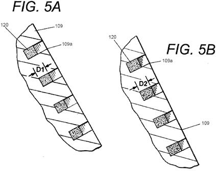
of the disclosure. FIG. 5A is a partial enlarged cross-sectional view of the
golf club head body shown in FIG. 4, and showing a piezoelectric member in a
first position. FIG. 5B is another partial enlarged cross-sectional view of the
golf club head body shown in FIG. 5A, and showing the piezoelectric member in a
second position.
[0054] In order to describe the features of the illustrative golf club head
102, a figure of a conventional golf club head is provided for reference at
FIG. 2. FIG. 2 is a partial cross-sectional view of a conventional golf club
head body 1000. As seen in FIG. 2, the conventional golf club head has grooves
which extend in a horizontal direction (i.e., a heel to toe direction) across
the golf club head body.
[0055] In contrast to the conventional golf club head shown in FIG. 2, the
illustrative golf club head 102 shown in FIG. 4A, may include one or more
piezoelectric members 120. For example, as seen in FIG. 4A, the piezoelectric
members 120 may be positioned to extend through the grooves 109a in the ball
striking face 109 of the golf club head 102. For example, the piezoelectric
members 120 may be configured as strips which extend substantially or entirely
through the length of grooves 109a (e.g., a heel to toe direction) in the ball
striking face 109 of the golf club head 102. It is noted that the piezoelectric
members 120 may have other configurations as well. For example, the
piezoelectric members 120 may be connected by a continuous plane of
piezoelectric material parallel to the ball striking face 109 (e.g., a face
plate). For example, the continuous plane of piezoelectric material may be
positioned at the rear of the piezoelectric members 120 so as to connect the
piezoelectric members 120. The continuous plane of piezoelectric material may
extend throughout some, or all, of the golf club head 102 at a position behind
ball striking face 109.
[0056] As described above, according to aspects of the disclosure, the electric
field may be applied to the piezoelectric member 120 through wires running
through the shaft 106 to deform the piezoelectric member 120. FIGS. 3 and 13
show such illustrative embodiments. Further, FIG. 4B is an illustrative
embodiment of such a structure according to aspects of the disclosure. As seen
in cross-sectional view shown in FIG. 4B, each of the piezoelectric member 120
may be connected to a lead or wire 140 through which the electric field may be
applied to the piezoelectric member 120. The lead or wire 140 may be connected
to the battery in the handle 107, such as shown in FIG. 3. For example, each
lead or wire 140 may be a branch of the wire that runs along the shaft of the
golf club 100 as seen in FIG. 3. It is understood that the lead or wire 140 may
be employed in various alternative configurations that will allow a suitable
electrical field to be applied to the piezoelectric member. It is further
understood that the lead or wire 140 can take various conductive member
configurations as necessary to impart the electrical field. It is noted that
for clarity purposes, leads or wires 140 connected to piezoelectric member 120
may not be shown in various other cross-sectional views throughout the
application.
[0057] It is noted that the piezoelectric members may be engaged with the golf
club head 102 by any viable means, such as: adhesives, cements, welding,
soldering, etc. Alternatively, the piezoelectric members may be formed
integrally with the golf club head 102. According to aspects of the disclosure
piezoelectric members may be injected into the golf club head 102. For example,
the piezoelectric material may be injected into cavities in the golf club head
102 that are configured to receive such piezoelectric material. Further,
according to aspects of the disclosure the golf club head 102 and the
piezoelectric members may be configured so that the engagement between the golf
club head 102 and the piezoelectric members retains the piezoelectric members
within the golf club head 102. For example, FIG. 4C is an illustrative
embodiment of such a structure according to aspects of the disclosure. As seen
in FIG. 4C, each of the piezoelectric member 120 may be configured with a
dovetail shape. Further, the golf club head 102 may include a corresponding
cavity configured to engage with the dovetail shape of the piezoelectric member
120. Thereby, such engagement between the golf club head 102 and the
piezoelectric members 120 retains the piezoelectric members within the golf
club head 102. It is noted that other structures of the piezoelectric material
and cavities may be used as well (e.g., other shapes for retaining the
piezoelectric material within the golf club head 102).
[0058] FIG. 5A illustrates the piezoelectric members 120 in the golf club head
102 in a first position (e.g., an original state) when no electric field has
been applied to the piezoelectric members 120. As seen FIG. 5A, the
piezoelectric members 120 have a first size which includes a depth of D1. In
contrast, FIG. 5B illustrates the piezoelectric members 120 in the golf club
head 102 in a second position (e.g., a deformed state) when an electric field
has been applied to the piezoelectric members 120. As seen FIG. 5B, the
piezoelectric members 120 have a second size which includes a depth of D2 which
is greater than D1. Hence, the volume of the grooves 109a of the golf club head
is reduced. Therefore, it is understood, that according to aspects of the
disclosure, the volume of the grooves 109a of the golf club head 102 may be
controlled (e.g., increased and deceased) by manipulating the piezoelectric
members 120 positioned in the grooves 109a in the ball striking face 109 of the
golf club head 102 (e.g., by applying an electric field to the piezoelectric
members 120).
..
.
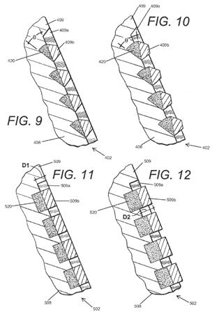
[0078] It is noted that several features of the embodiment shown in FIGS. 9 and
10 are similar to the embodiments described above and, therefore, for the sake
of brevity will not be elaborated on in detail here. However, it is noted that
according to aspects of the disclosure and as illustrated in the embodiment
shown in FIGS. 9 and 10, the piezoelectric members 420 may be configured within
the golf club head 402 to selectively control and adjust the angle of the
grooves 409a of the golf club head 402. Hence, as will be discussed below,
according to aspects of the disclosure, the piezoelectric members 402 may be
used to selectively control and adjust the amount of spin the golf club head
402 imparts to the golf ball during a golf shot.
[0079] As seen in the illustrative embodiment shown in FIGS. 9 and 10,
according to aspects of the disclosure, the piezoelectric members 420 may be
configured to be positioned behind the individual slat 409b in the ball
striking face 409 which at least in part defines the grooves 409a of the ball
striking face 409 of the golf club head 409. For example, as seen in FIGS. 9
and 10, the piezoelectric members 420 may be configured to extend substantially
or entirely behind each individual slat 409b in the ball striking face 409 of
the golf club head 402. Further, as seen in FIGS. 9 and 10, according to
aspects of the disclosure, piezoelectric members 420 may be configured such
that the depth, or thickness, of the piezoelectric member 420 may vary with the
height of the piezoelectric member 420. For example, as seen in FIGS. 9 and 10,
the thickness of the piezoelectric members 420 is greater at the upper portion
of each of the piezoelectric members 420 than the lower portion of each of the
piezoelectric member 420. For example, the upper portion of the piezoelectric
members 420 may each have a thickness in the range of 1.0-1.4 mm and the lower
portion of each of the piezoelectric member 320 may have a thickness in the
range of 0.5-0.7 mm. Further, as will be discussed below, the piezoelectric
member 420 may include an angled configuration.
[0083] According to aspects of the disclosure, piezoelectric material may be
incorporated into a golf club head still in other ways to selectively control
or adjust other attributes of the golf club head. For example, according to
aspects of the disclosure piezoelectric material may be configured within the
golf club head to control the depth or thickness of the slats in the ball
striking face of the golf club head. For example, FIGS. 11-12 illustrate an
alternative embodiment of a golf club head body according to aspects of the
disclosure. Specifically, FIG. 11 shows a cross-sectional view of an
illustrative embodiment of the golf club head 502 according to aspects of the
disclosure wherein piezoelectric members 520 are in a first position. FIG. 12
shows a cross-sectional view of the illustrative embodiment of the golf club
head 502 according to aspects of the disclosure wherein piezoelectric members
520 are in a second position.
..
.
[0090] As mentioned above, while the disclosure has been described primarily in
terms of use in an iron-type golf club head (including iron type-hybrid golf
club heads), those skilled in the art will appreciate that aspects and features
of this disclosure are not limited to use with iron-type golf club heads. For
example, if desired, putter-type and/or wood-type body members may be
substituted for the iron-type club head body members illustrated in FIGS. 1 and
3-12, and the same or similar features and/or structures could be included in a
putter or wood structure without departing from this disclosure. For example,
FIG. 14 illustrates an embodiment according to aspects of the disclosure in
which a putter-type golf club head 602 is configured with a plurality of
piezoelectric members 620 engaged with grooves of in the ball striking face 609
of the putter-type golf club head 602. In this way the volume of the grooves
609a can be adjusted in a manner similar to that described above with regard to
the embodiment shown in FIGS. 1 and 3, 4, 5A and 5B. Hence, it is understood
that any of the various features described above may be incorporated into
various types of golf club heads and golf club structures including iron-type,
wood-type, hybrid-type, putter-type, etc., golf club heads and golf club
structures.

What do you think, will we ever see irons with piezoelectric adjustable grooves?