
Putting Woes? This Golf Invention May be the Solution
This week a patent was granted on a unique putting aid that has made me look at my putting stroke in a different light. The patent issued as USPN 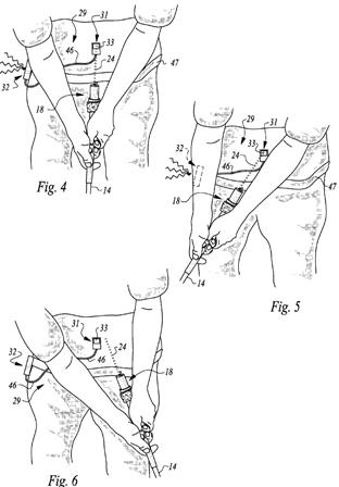
The patent goes on to say:
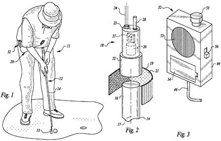
The golf swing training device 11 disclosed herein is used in connection with a golf club, namely, a putter 12. Putter 12 includes a head 13, and a shaft 14 having an upper end 16. Putter 12 also has a longitudinal axis 17, shown in FIG. 2. Although the device 11 is primarily intended for use with training golfers in the use of putters, it may also be used with other golf clubs, where the stroke is similar to that of a putter.
An illuminator 18 is mounted on the upper end 16 of the shaft 14 by any convenient means. For example, a strip 19 of hook and loop material having an inner adhesive side 21 provides a simple and inexpensive means of attachment. One advantage of this arrangement is that the illuminator 18 can easily be removed either for service or to return the putter 12 to an unmodified condition. Lower coupler section 22 of illuminator 18 could also be screwed over the upper end 16 of shaft 14, provided both structures are provided with complementary threads (not shown). Or, coupler section 22 could simply be adhesively attached over upper end 16.
Illuminator 18 preferably includes a laser diode 23, producing a beam 24 of light wave energy. The 3 mw laser diode 23 provides an intense, collimated output anywhere within the general range of 640 nm to 760 nm. This red color frequency range is selected because it can readily be seen by the golfer during the day or night, and it can also be detected by many different light sensors. A laser diode also provides the advantage of having low power consumption, a desirable attribute for use in illuminator 18, a battery powered device. However, an LED or other source of light wave energy providing sufficient intensity at an appropriate light wave frequency may also be substituted.
Laser diode 23 is powered by a battery 26, providing low voltage DC to a driver 27. A switch 28 enables the golfer to turn illuminator 18 on and off as desired. Driver 27 is a conventional and inexpensive 555 timer, providing a stable current output at an AC frequency of approximately 1 khz, effective to pulse encode the beam 24 produced by laser diode 23. This frequency is not critical, but it is high enough to provide a light wave source which can be differentiated from the DC frequency of ambient light. This frequency of 1 khz is also low enough to minimize charge/discharge losses caused by capacitive reactance in the laser diode drive circuit.
As is evident from FIG. 2, beam 24 is directed away from the shaft 14 of putter 12, along a path which is generally coincident with and parallel to, the longitudinal axis 17 of the shaft 14. Laser diode 23 could also be located so that beam 24 is directly coincident with longitudinal axis 17, but for purposes of practicing the invention, it is only necessary that the beam 24 be generally coincident with and parallel to that axis. This direction and orientation for beam 24 ensures that the axis of putter 12 will be accurately projected onto the golfer so it can be detected and the golfer appropriately alerted.
For that purpose, a detector assembly 29 is provided, including a light sensor 31 and a transducer 32. Light sensor 31 includes a polycrystalline photovoltaic cell 33, selected for its ability to generate an AC square wave output 34 responsive to the beam 24, even in the presence of high levels of ambient light produced by the sun. Cell 33 also has the characteristic of being relatively large in size, on the order of 1” square, for practical use in the present application.
Light sensor 31 also includes a housing 36 to secure cell 33 and to provide a convenient means for attaching sensor 31 to the clothing of the golfer. Typically, the light sensor 31 is worn by the golfer during the training session, being strategically located around the stomach region of the golfer to define a target for the beam 24. During a putting stroke, it is generally advantageous for consistency and accuracy in the shot, to maintain the longitudinal axis 17 of the putter 12 directed toward the stomach of the golfer. Each golfer can experiment to find a particular location for light sensor 31, for example somewhere between the belt region to the upper stomach region, which is optimum for his putter and unique style of golfing. In any event, housing 36 may be attached to the clothing of the golfer by any convenient means including hook and loop strips, clips, or pins. (not shown).
Housing 36 also provides a structure for a detachable shroud 37, providing a number of additional features. After a golfer has achieved a certain level of expertise and skill, it may be desirable to reduce the effective size of the target provided for the illuminator 18. For that purpose, shroud 37 including a circular cutout 38 may be clipped over the housing 36. The shroud 37 thereby reduces the exposed area of cell 33, and changes the target from a square configuration to a circular configuration. (See, FIGS. 9 and 10). It is apparent that the size and configuration of the cutout can be varied, depending upon the needs of the golfer.
In addition to the feature of varying the target size and configuration, an optical bandpass filter 39 may be included in circular cutout 38 to provide another operational feature. The light wave transmission characteristics of optical bandpass filter 39 are selected to pass light wave energy produced by the illuminator 18, and to absorb ambient light wave energy produced by the sun. The optical bandpass filter 39 will increase the signal to noise ratio of the system, and therefore the reliability of the operation of the transducer 32.
.
.
.
As its first internal component, transducer 32 includes a high pass filter 48. High pass filter 48 has a low frequency cutoff of 100 hz, and provides 6 db of loss for all signals below that frequency. This filter has proven effective in removing all ambient light DC output from the photovoltaic cell 33. The output of high pass filter 48 is then fed to amplifier means 49, to increase the amplitude of the detected square wave signal. A common and very high gain LM339 comparator chip was selected for amplifier means 49, to clean up and amplify the weak square wave signal outputted from high pass filter 48. The output of amplifier means 49 is effective to drive a either a buzzer or a vibrator 51.If a buzzer is employed, the aural output passes through grill 52 in housing 44. If a vibrator is used in transducer 32, the vibrator is mechanically coupled to the housing 44. As shown in FIG. 3, housing 44 also includes an on-off push button switch 53
to turn the transducer 32 on or off. A battery door 54 is also provided, to allow convenient access for battery replacement.In operation, the transducer 32 produces a buzzing sound or a vibrating sensation, whenever the light sensor 31 detects the light beam 24 outputted from the illuminator 18. This buzz or vibration alerts the golfer that the club is following a correct path and position through the course of the golf swing. With such sensory feedback, the golfer develops muscle training for a consistent and correct swing pattern. This operation is depicted in FIGS. 4-6. As can be seen in FIGS. 4 and 5, the golfer has maintained the correct position of the club from the beginning of the swing up to and including the end of the backstroke. However, in FIG. 6, it is evident that the beam 24 has strayed from the target presented by the light sensor 31, indicating an incorrect position for the golfer’s hands and arms as they are holding the shaft 14. By the time the club has reached the position shown in FIG. 6, the buzzing sound or vibrating sensation will have ceased, indicating to the golfer that correction is needed. Once correction of the position of the club throughout the entire stroke has been made, the golfer will experience continuous sensory feedback of that fact.
In the event the golfer learns better through a reverse sensory feedback, a reverse mode switch 56 is also provided on the side of housing 44. When reverse mode switch is activated, it is effective to reverse the operation of the transducer 32 so that it produces a buzzing sound or a vibratory sensation in the absence of a detected light beam 24.
Surely I am not the only golfer that never considers where the putter grip butt end is pointing during a stroke; am I? Regardless, that is a great idea. Where can I buy one?
David Dawsey – Keeping an Eye on Golf Practice Inventions
PS – click HERE to read interesting golf ball patent posts