
More PING Groove Ideas
There has been no shortage of interesting groove inventions lately. For instance, HERE is a post regarding Acushnet grooves, HERE is a post regarding Karsten Manufacturing (aka PING) grooves, and HERE is a post regarding Bridgestone grooves.
This week another Karsten patent application published related to grooves. The application published as US Pub. No. 20090209361 titled “Golf Club Heads with Grooves and Methods of Manufacture.” The following figures illustrates the concept nicely.
The application explains:
[0036] Grooves 112 can be compliant or non-compliant with, for example, the regulations regarding grooves that were proposed by the United States Golf Association (USGA) on Feb. 27, 2007. As an example, when compliant with these proposed regulations, grooves 112, including groove 113: (1) are straight and parallel with each other; (2) have a symmetrical cross-section and have sidewalls that do not converge toward the groove opening; (3) have a width, spacing, and cross-section that is consistent throughout the impact area of front face 111; (4) have a width that does not exceed 0.9 millimeters (mm) using the USGA’s thirty degree method of measurement; (5) have a distance between adjacent grooves that is not less than three times the width of the grooves and that is not less than 1.905 mm; (6) have a depth that does not exceed 0.508 mm; and (7) have a cross-sectional area divided by a groove pitch (i.e., groove width plus spacing between adjacent grooves) that does not exceed 0.064 mm.sup.2/mm. Additional details regarding grooves 112 are explained in the subsequent figures.
[0037] FIG. 2 depicts a cross-sectional view of a portion of groove 113 of golf club head body 110 (FIG. 1). The cross-section view of FIG. 2 is defined by dashed region 122 in FIG. 1. As depicted in FIG. 2, groove 113 has edges 210 and 211, sidewalk 220 and 221, and bottom 230. Edge 210 is adjacent to and couples front face 111 and sidewall 220, and edge 211 is adjacent to and couples front face 111 and sidewall 221. Bottom 230 is adjacent to and couples sidewalls 220 and 211. Edges 210 and 211 can also be referred to as borders. Groove 113 has depth 231, as defined by a substantially perpendicular distance between front face 111 and bottom 230.
[0038] Groove 113 can have a variety of overall cross-sectional shapes including, but not limited to, a U-shape, a V-shape, a rectangular-shape, a square-shape, and the like. In the embodiment illustrated in FIG. 2, groove 113 is symmetric such that edges 210 and 211 are substantially mirror images of each other, sidewalls 220 and 221 are substantially mirror images of each other, and the left and right halves of bottom 230 are substantially mirror images of each other. In a different embodiment, groove 113 can be asymmetric such that edges 210 and 211 are different from each other, sidewalls 220 and 221 are different from each other, and/or the left and right halves of bottom 230 are different from each other.
[0039] Turning to FIG. 3, a portion of edge 210 is depicted. The portion of FIG. 3 is defined by dashed region 233 in FIG. 2. As depicted in FIG. 3, edge 210 has an overall convex curve shape. Within that overall shape, however, edge 210 is unsmooth or uneven because edge 210 comprises one or more protrusions 330, which do not include the overall shape of edge 210. Also, FIG. 3 illustrates edge 210 to include five of protrusions 330, but edge 210 can include more or less than five of protrusions 330. Furthermore, protrusions 330 have peaks or peak points that remain below front face 111 and do not extend out of groove 113 (FIG. 2), but in a different embodiment, the peaks do not remain below front face 111 and/or do extend out of groove 113 (FIG. 2). In one embodiment, the peaks of protrusions 330 do not create an overall sharpness for edge 210, as best seen in FIG. 2. Additional details regarding protrusions 330 are described below.
[0040] Referring briefly back to the embodiment depicted in FIG. 2, the protrusions at edge 210 do not form a raised lip or a sharp edge for edge 210 or groove 113. Also, edge 211 is symmetric with edge 210 such that edge 211 is also unsmooth in the same manner as edge 210. In a different embodiment, edge 211 is unsmooth in a different manner than edge 210 (i.e., a different number, shape, or size of protrusions).
[0041] In another embodiment, still referring to FIG. 2, edge 211 is smooth while edge 210 is unsmooth. In this embodiment, the bottom edges of grooves 112 (FIG. 1) (i.e., the edges of a groove that are closer to sole 117 of golf club head body 110) can be smooth while the top edges of grooves 112 (FIG. 1) (i.e., the edges of a groove that are closer to top rail 118 of golf club head body 110) can be unsmooth.
[0042] In a further embodiment, edge 211 is unsmooth while edge 210 is smooth. In this embodiment, the bottom edges of grooves 112 (FIG. 1) can be unsmooth while the top edges of grooves 112 (FIG. 1) can be smooth.
[0043] The unsmooth or uneven characteristic of edge 210 (and/or edge 211 (FIG. 2)) can be defined by as one example, two or more inflection points. The unsmooth or uneven characteristic of edge 210 can produce a sharp corner for edge 210, or the unsmooth or uneven characteristic of edge 210 can produce a non-sharp or even a dull corner for edge 210.
[0044] The unsmooth or uneven characteristic of edge 210 and/or edge 211 can, under certain conditions, increase the grip that front face 111 (FIG. 1) has on a golf ball when front face 111 of golf club head body 110 (FIG. 1) impacts the golf ball. As a result of the increased or improved grip, the golf ball can, under certain conditions, have a higher rate of backspin, which can, under certain conditions, improve the consistency of a golf shot from golf club 100 (FIG. 1) in a variety of playing conditions.
[0045] As also depicted in FIGS. 2 and 3, protrusions 330 are located at edge 210 and/or edge 211, but are absent from sidewalls 220 and 221. In a different embodiment, protrusions 330 can also be located at one or both of sidewalls 220 and 221. This different embodiment can be useful if front face 111 and/or edges 210 and 211 are soft or otherwise deformable so that protrusions 330 at sidewalls 220 and 221 can grip the golf ball when front lace 111 impacts the golf ball.
[0046] Protrusions 330 can also be referred to as projections and can include protuberances, extensions, and undulations. As best seen in FIGS. 2 and 3, protrusions 330 can be substantially parallel to groove 113. Accordingly, in an embodiment where each edge of grooves 112 (FIG. 1) have protrusions 330, each of protrusions 330 can be parallel to each of grooves 112.
[0047] Protrusions 330 can be regularly or irregularly shaped. Protrusions 330 can also be symmetric (vertically, horizontally, or otherwise) such that a first half of a protrusion is substantially a mirror image of a second half of the same protrusion, or protrusion 330 can be asymmetric such that a first half of a protrusion is different from a second half of the same protrusion. Protrusions 330 can further be symmetric such that a first one of protrusions 330 is substantially a mirror image of a second one of protrusions 330, or protrusions 330 can be asymmetric such that a first one of protrusions 330 is different from a second one of protrusions 330.
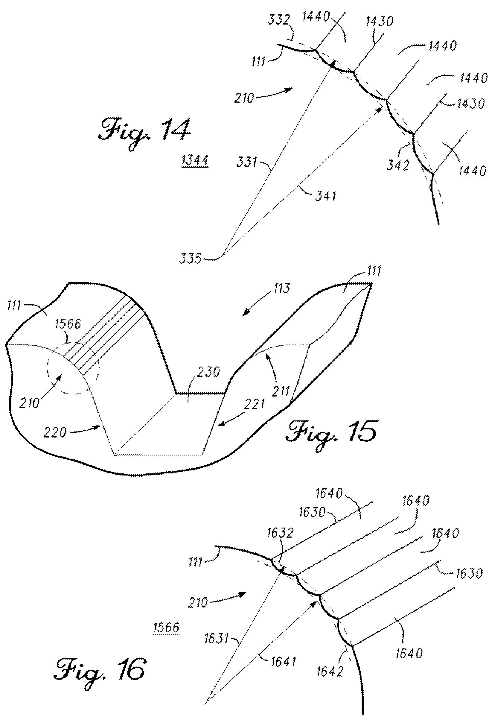
[0048] Protrusions 330 have peaks and concave sides. The concave sides between adjacent protrusions 330 define valleys 340. Accordingly,
protrusions 330 can have a scallop-like configuration, as depicted in FIG. 3, but other configurations are also contemplated, as shown in the subsequent figures.[0049] The peaks of protrusions 330 in FIG. 3 define curve 332. Curve 332 is represented by a dashed line in FIG. 3, and curve 332 has a radius 331. Similarly, the bottom portions of valleys 340 define curve 342. Curve 342 is represented by another dashed line in FIG. 3, and curve 342 has radius 341. As depicted in FIG. 3, curves 332 and 342 are concentric or parallel with each other; radii 331 and 341 originate from the same point 335; and radius 341 is smaller than radius 331. In one embodiment, each of radius 331 and radius 341 is greater than or equal to approximately 0.254 mm. In another embodiment, each of radius 331 and radius 341 is greater than or equal to approximately 1.016 mm. Either one or both of radius 331 and radius 341 can be referred to as an effective radius of edge 210, and in the same or different embodiment, each edge of grooves 112 (FIG. 1) can have radius 331 and radius 341, or only one edge of each of grooves 112 (FIG. 1) cart have radius 331 and radius 341 while the other edge of each of grooves 112 (FIG. 1) has radius 341.
[0050] Referring back to FIG. 1, one or more other ones of grooves 112 can be similar, identical, or symmetric to groove 113. In one embodiment, groove 113 is asymmetric, but each of grooves 112 is symmetric with groove 113. As another example, in another embodiment, groove 113 is symmetric, and every second one or every third one of grooves 112 is symmetric with groove 113. In this embodiment, the ones of grooves 112 that are not symmetric to groove 113 can have a different cross-sectional shape, one smooth edge and one unsmooth edge, one or two edges with a different number of protrusions, a different shape of protrusions, and/or a different height or with of protrusions. Other variations are also contemplated herein.
[0051] Turning to FIG. 4, a proposed USGA measurement of the sharpness of edge 210 of groove 113 of FIGS. 2 and 3 is depicted. In particular, FIG. 4 shows two dashed concentric circles 442 and 444 having radii 441 and 443, respectively. The smaller circle, circle 442, is tangential to front face 111 and to sidewall 220, and sidewall 220 has an angle 443.
[0052] Edge 210 is not sharp and is in compliance with the aforementioned proposed USGA regulations regarding grooves when:
[0053] In one embodiment, edge 210 can be defined by the portion of groove 113 that is located within circles 442 and 444. In the same or different embodiment, edge 210 is defined as being located between front face 111 and sidewall 220. In one example of this embodiment, front face 111 and sidewall 220 can be flat such that edge 210 is the non-flat portion located between the flat surfaces of front face 111 and sidewall 220. Other configurations for edge 210 are also contemplated herein.
[0054] Referring back to FIG. 3, protrusions 330 protrude or extend from edge 210. Arrow 350 shows a direction that a drill bit or micromachining tool can move along edge 210 to form valleys 340 and protrusions 330 after casting, forging, machining, or otherwise forming front face 111 and/or golf club head body 110 (FIG. 1). In one embodiment, each of valleys 340 represents a single cut or pass of a micromachining tool along edge 210. In a different embodiment, a single cut or pass of a micromachining tool along edge 210 can simultaneously form two or more of valleys 340.
Amazing dedication to spin.
Dave Dawsey – Monitoring Golf Groove Technology
PS – check out the post “Is Your Wedge Lacking the Appropriate Traces?” regarding another Bridgestone invention designed to help with spin
PPS – also check out the post “Does Your Club Face Need Some Engineered Texturing? Taylor Made Thinks So!”
PPPS – check out other golf iron invention posts HERE