
Golf Shoe Spike Patent Infringement – This Time Greenkeepers is on the Receiving End
One year ago I wrote about a golf spike patent infringement lawsuit in which Greenkeepers sued Acushnet (FootJoy) and Softspikes for alleged patent infringement of USPN 6530162 titled “Sports Shoe Cleats.” Click HERE to review the post. Interestingly, this was not the first lawsuit centered on the ‘162 patent.
Yesterday Greenkeepers found themselves in a different position; namely that of a defendant in a patent infringement lawsuit brought by Trisport, Ltd. concerning USPN 6810608 titled “Shoe Cleats.” Click Fast Twist system works. Check out the following description and drawings from the patent.
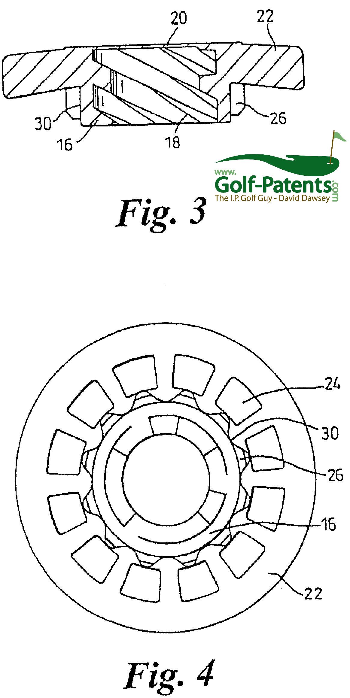
The stud is arranged for securement in a sole or heel of a golf shoe by means of a holder in the form of a socket-forming receptacle (FIGS. 3 and 4). The receptacle comprises a hub 16 having a screw-threaded socket bore 18, the bore of the hub being closed at its upper end 20. A flange 22 surrounds the hub, the flange being formed with perforations 24. For use the receptacle is incorporated into a moulded or composite outsole (or heel) of a golf shoe so as to present its screw-threaded bore 18 for reception of the complementarily threaded spigot 12 of the stud, so to secure the stud to the shoe. The receptacle is formed as a unitary moulding of a plastics material.
Such a stud and receptacle combination, as so far described, is well known in the art.
In the invention, the complementary thread forms of the stud and receptacle are three-start threads, providing a relatively steep helix angle which enables the stud to be inserted into the receptacle with a minimum of rotation. In order to secure the stud when screwed into the receptacle, the frictional resistance to unscrewing being relatively low owing to the steepness of the thread, a locking means is used. This comprises a ring of axially extending teeth 26 which are formed around the outside of the receptacle hub 16 to become engaged with inner surfaces of a collar 28 on the stud as the hub is inserted into the collar.
As seen in FIGS. 3 and 4, the teeth 26 project radially outwards from a cylindrical outer surface 30 of the hub, the teeth being in the form of short stubby ribs which extend in a direction parallel to the axis of the hub. In cross-section the ribs have a generally triangular form but present a rounded apex. The ribs are uniformly distributed co-axially about the hub axis, there being twelve ribs provided at 30.degree. intervals.
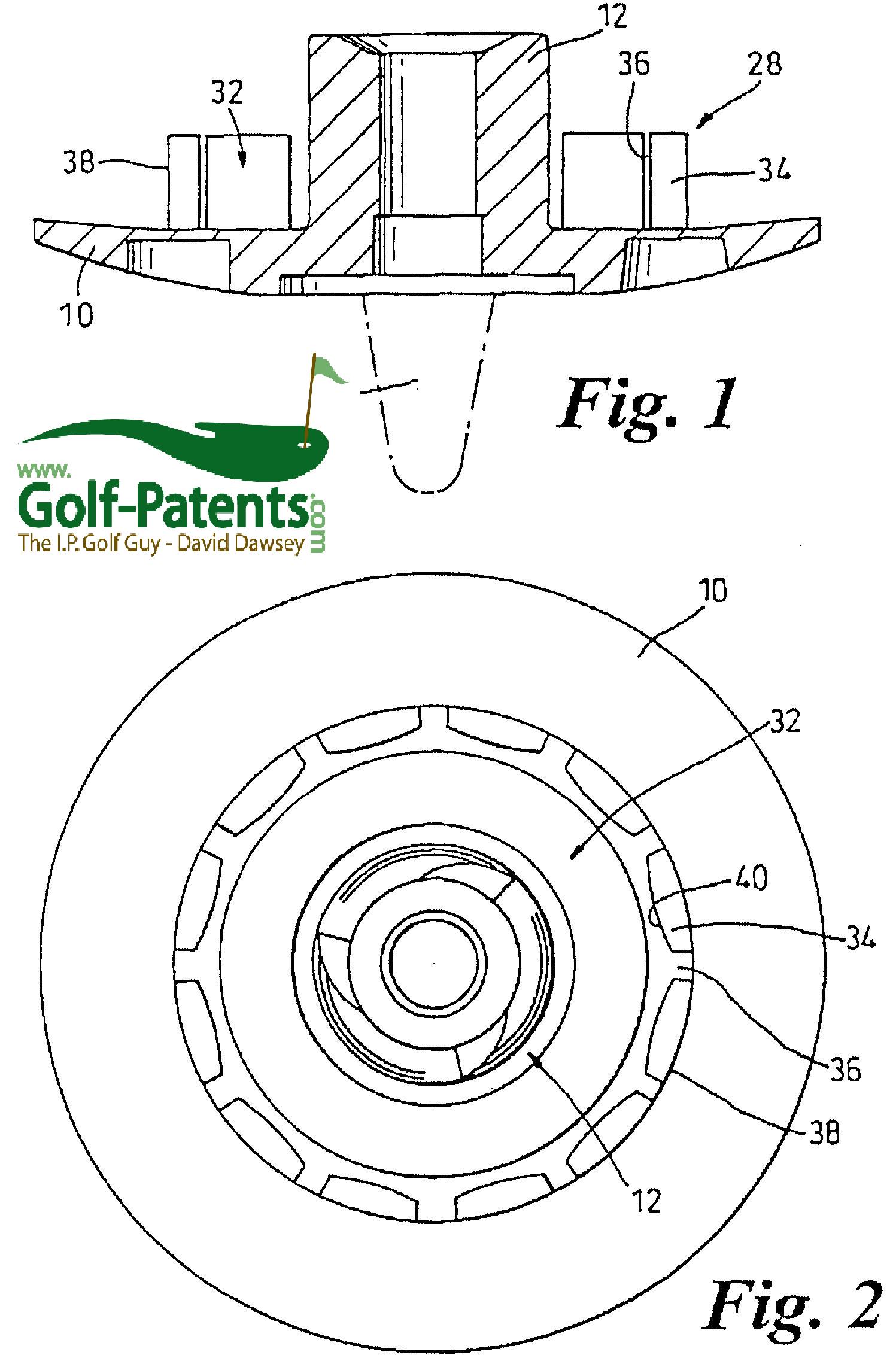
The stud collar 28 (FIGS. 1 and 2) extends axially from the flange 10, being approximately half the height of the threaded spigot 12 which it surrounds coaxially. An annular well 32 is formed between the spigot 12 and the collar 28 for reception of the receptacle hub 16. The collar 28 comprises a ring of twelve separate segments forming free-standing posts 34 which are uniformly distributed at 30.degree. intervals about the axis of the stud, the posts being separated by narrow slits 36. Radially outer surfaces 38 of the posts make up a cylindrical outer surface of the collar. Radially inner surfaces 40 of the posts (facing towards the teeth 26 in assembly) are slightly convex in planes perpendicular to the stud axis (FIG. 2) to present an inner surface of the collar which, interrupted by the slits 36, generally undulates in a circumferential direction about the stud axis.
The distance of radial projection of the teeth 26 from the receptacle axis is substantially equal to that of the inner surfaces of the posts 34 at circumferential positions immediately adjacent to the slits 36. That is to say, other than when the receptacle teeth 26 are radially aligned with the collar slits 36 there is radial interference between the teeth and the posts which causes frictional resistance to relative rotation of the components. Rotation of the stud relative to the receptacle is, therefore, resisted in steps by engagement of the teeth 26 with successive posts 34. This is the case whether the stud is fully inserted into the receptacle or only partially inserted (provided the degree of insertion is such that the teeth and the posts are interengaged).
The teeth 26 are substantially incompressible and reliance is placed on resilient deflection of the free-standing posts 34 to ease the passage of the teeth past the posts during relative rotation of the components. The convex surface profile of the posts 34 smoothes the passage of the teeth 26 across the surfaces of the posts between engagements of the teeth in the recesses formed between the spaced posts. As the spigot 12 is screwed into the socket, the posts 34 are less easily deflected, and so offer increasing resistance to passage of the teeth past them (as the teeth approach the bases of the posts at the flange 10) which serves to militate against any danger of overtightening the stud into the receptacle. Upon rotation of 120.degree. of the spigot relative to the socket, after initial interengagement of the spigot and socket threads, the stud is fully inserted into the receptacle. In this position, the teeth 26 of the receptacle are in opposition to the slits 36 between the posts 34 of the stud collar.
The locking posts 34 on the stud physically deform outwardly as they pass over the locking teeth 26 on the receptacle and return into position when engaged into the recesses between the teeth. This physical movement is not dependent on the thread clearances and it is not affected by the thread geometry, permitting the two components of the thread assembly to be intimately coupled and thereby giving strength, resistance to stripping and easy location of the mating parts at assembly.
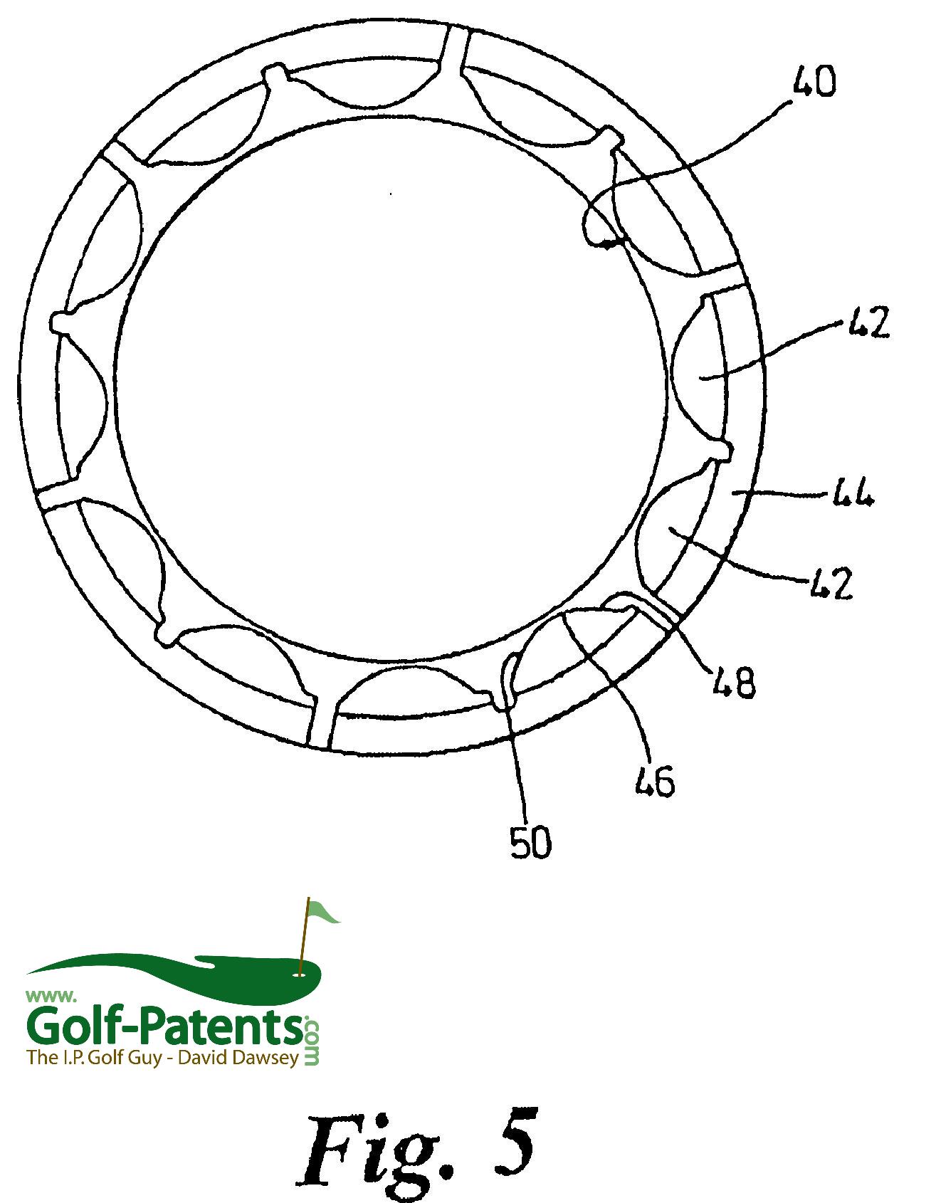
FIG. 5 shows a further embodiment of the collar 28 on the stud, and corresponding reference numerals have been applied to corresponding parts. Instead of the separate posts 34, in FIG. 5 posts 42 are in pairs, each pair sharing a common base 44. The radially inner surfaces 40 of each post 42 are also different. Although still generally convex towards the teeth, the circumferential ends of the surfaces are not mirror-symmetrical. Instead, each surface 40 has a central convex region 46, a first circumferential end 48 having a concave profile towards the teeth, and a second circumferential end 50 having a convex profile towards the teeth. The first end 48 is the leading end and the second end 50 is the trailing end when the stud is inserted in the holder, and vice versa when it is removed.
The concave profile of the first end 48 presents less resistance to the teeth on insertion of the stud, while the convex profile of the second end 50 presents greater resistance on removal. This enables the stud to be inserted relatively easily, but prevents its accidental removal.
The profiles of the ends 48, 50 may be varied to vary the torque needed for screwing and unscrewing or to allow for different frictional and resilience characteristics of different materials.
Goodness, it is getting to the point that I have a hard time keeping track of all the golf industry patent infringement lawsuits!
David Dawsey – Monitoring Golf Shoe Litigation
PS – click HERE to read about more litigation in the golf industry