
Does the Golf Ball of the Future Have a Variable Thickness Cover?
In the golf industry the term “variable thickness” generally relates to the thickness of the face of a golf club, not a golf ball. Perhaps someday this will change.
Why? Because a recently issued Acushnet patent is directed to just that. The patent provides a nice overview of the issues associated with golf ball manufacturing, specifically:
BACKGROUND OF THE INVENTION
Conventional golf balls can be divided into two general classes: solid and wound. Solid golf balls include one-piece, two-piece (i.e., single layer core and single layer cover), and multi-layer (i.e., solid core of one or more layers and/or a cover of one or more layers) golf balls. Wound golf balls typically include a solid, hollow, or fluid-filled center, surrounded by a tensioned elastomeric material, and a cover.
Examples of golf ball materials range from rubber materials, such as balata, styrene butadiene, polybutadiene, or polyisoprene, to thermoplastic or thermoset resins such as ionomers, polyolefins, polyamides, polyesters, polyurethanes, polyureas and/or polyurethane/polyurea hybrids, and blends thereof. From the perspective of a golf ball manufacturer, it is desirable to have materials exhibiting a wide range of properties, such as resilience, durability, spin, and “feel,” because this enables the manufacturer to make and sell golf balls suited to differing levels of ability and/or preferences. In this regard, playing characteristics of golf balls, such as spin, feel, CoR and compression can be tailored by varying the properties of the golf ball materials and/or adding additional golf ball layers such as at least one intermediate layer disposed between the cover and the core. Intermediate layers can be of solid construction, and have also been formed of a tensioned elastomeric winding. The difference in play characteristics resulting from these different types of constructions can be quite significant.
Conventionally, golf balls are made by molding outer layers about a core. Typically, outer layers are formed about the spherical outer surface of an innermost golf ball layer via compression molding, casting, or injection molding. Injection molding typically requires a mold having at least one pair of mold cavities; e.g., a first mold cavity and a second mold cavity, which mate to form a spherical recess. In addition, a mold may include more than one mold cavity pair. In one injection molding process, each mold cavity includes retractable positioning pins to hold the core in the spherical center of the mold cavity pair. Once the core is positioned in the first mold cavity, the respective second mold cavity is mated to the first to close the mold. A cover material is then injected into the closed mold. The positioning pins are retracted while the cover material is flowable to allow the material to fill in any holes caused by the pins. When the material is at least partially cured, the covered core is removed from the mold (de-molded).
Casting is a common method of producing a urethane, urea or urethane/urea hybrid outer layer about a core or other subassembly. A desired benefit of casting golf ball layers about subassemblies is that the resulting layer has a substantially uniform thickness. In a casting process, a castable composition is introduced into a first mold cavity of a given pair of mold half shells. The core/subassembly is then either placed directly into the composition or is held in position (e.g., by an overhanging vacuum or suction apparatus) to contact the material in what will be the spherical center of the mold cavity pair. Once the castable composition is at least partially cured (e.g., to a point where the core will not substantially move), additional castable composition is introduced into a second mold cavity of each pair, and the mold is closed. The closed mold is then subjected to heat and pressure to cure the composition, thereby forming the outer layer about the core. The mold cavities can have smooth surfaces or include a negative dimple pattern to impart dimples in the composition during the molding process where the cast layer is a cover, for example. It is important that a core/subassembly be centered in the castable composition within a mold cavity before the mold halves are mated because a non-centered core/subassembly can create and result in undesirable playing characteristics.
Compression molding or retractable pin injection molding (RPIM) are methods commonly used to form ionomer covers around solid or dual polybutadiene (PBD) cores. Compression molding involves using multiple pairs of hemispherical cups with respective cavities which when combined form a spherical recess for receiving and housing the core. The pair of hemispherical cups are placed into compression mold cavities and closed about the core which is placed between the hemispherical cups. The core and cover combination is then exposed to heat and pressure, which cause the hemispherical cups to combine and form a full cover.
However, it is well known in the art that compression molding a thin cover over a large and/or soft core can cause a “blow out” of the core due to severe deformation of the soft core as the mold is closed. Also, it is very difficult to obtain acceptable roundness of the molded golf ball especially with softer (25-70 Atti/PGA) and larger cores (greater than 1.530”). Excessive core shifting is another major issue encountered. Similar issues have been experienced with RPIM technology due to forces resulting from “pinching” of retractable pins to hold softer polybutadiene (PBD) cores in the center and “hard to control” multi-directional plastic fluid forces during injection will greatly shift PBD cores as well as produce unacceptable out-of-round product. Variations in final golf ball characteristics such as compression, weight, size, roundness, and layer adhesion therefore occur.
Consequently, a practice called “bumping” has been used in the production of compression molding about PBD cores in order to aid in releasing residual air in the mold cavity. With this technique, the mold is clamped for a short time (at least 15 seconds), and then unclamped to allow the residual air to release. This became standard practice in compression molding for over twenty years and is described in U.S. Pat. No. 6,838,036 of Sugimoto.
More recently, improvements have been directed to making the steps of a compression molding process more controllable. For example, one advance replaces pre-set cycle times with instrumentation for monitoring the compression molding press, its molds and tooling, along with its facilities, to gather and use feedback from the process to actively dictate press movement and to time the process in order to produce a more consistent product. See U.S. Pat. No. 7,927,524 (“‘524 patent”) and U.S. Pat. No. 8,309,002 (“‘002 patent”) of Vora et al., each hereby incorporated by reference herein in its entirety.
Despite being better able to control the steps of the compression molding process, numerous instances of “blowout” and “cup shifting” have continued to occur when compression molding a thin cover/outer layer over a large and soft core. And unfortunately, when blowout occurs, it rarely happens in a single or merely a few instances but rather with respect to many if not most of the cores involved in the run.
For example, ionomer blends containing higher levels of FUSABOND.RTM. (e.g., about 20-35 wt. %) can deliver soft feel and distance but tend to produce such blowout when incorporated in conventional compression molding cups that are compression molded over large, soft cores. As a result, golf ball manufacturers have instead turned to alternatives such as very low modulus ionomers (VLMI), which provide soft feel, but not the distance that an ionomer blend containing FUSABOND.RTM. in amounts of about 20-35 wt. % could.
It would therefore be beneficial to develop improvements to the configuration and geometry of the hemispherical molding cups themselves in order to expand and extend options for compression moldable materials to include desirable compositions such as ionomer/FUSABOND.RTM. blends containing up to 20%-35% or greater FUSABOND.RTM.. Such improved hemispherical cups would be particularly useful if useable within existing compression molding processes after small tooling modifications and without meanwhile sacrificing desirable playing characteristics typically produced by such golf balls, namely soft feel accompanied by good distance.
The current inventive golf balls incorporating novel hemispherical cups and methods of making such golf balls address and solve these needs.
OK, we got it – making a golf ball is harder than it looks!
So, what’s the deal with the variable thickness cover? Won’t that screw up the weight distribution or shape of the ball? Nope, the finished product will have a uniform final cover thickness. This invention is all about improving the compression molding process, and starting that process with variable thickness covers has distinct benefits. I will let the patent explain:
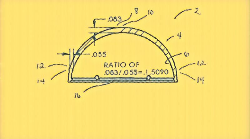
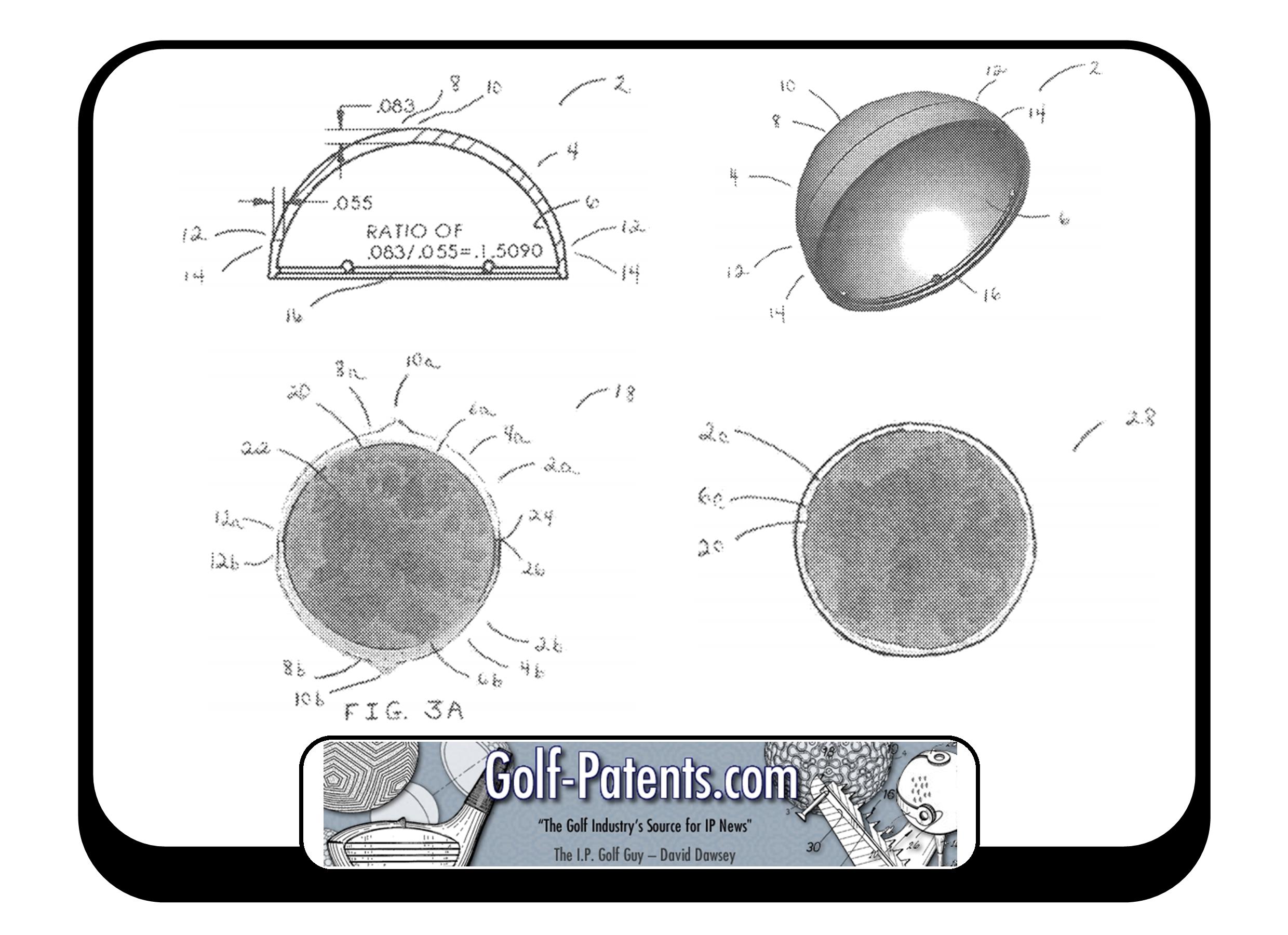
Additionally, the first and second hemispherical cups have a thickness that tapers from a top section to a bottom section, and meanwhile, a cup thickness ratio of a top section thickness to a bottom section thickness is from about 1.10 to 1.70. Meanwhile, the top section thickness may be any thickness which, when coordinated with the bottom section thickness in the ratios defined herein, may be compression molded about the large, soft subassembly/core as a resulting outer layer having a uniform compression molded thickness of from about 0.015 inches to about 0.055 inches. And consistent with the cup thickness ratio, the bottom section thickness is always less than the top section thickness. FIG. 1 and accompanying discussion thereof herein reveal one possible inventive hemispherical cup construction wherein the top section thickness is 0.083 inches and the bottom section thickness is 0.055 inches and the resulting cup thickness ratio is therefore (0.083/0.055) or 1.5090.
.
.
.
The thickness of each hemispherical cup 2 tapers from top section 8 to bottom section 12 such that a cup thickness ratio of top section thickness to bottom section thickness is from about 1.10 to 1.70. Meanwhile, inner surface 6 is sized, shaped and contoured to receive and conformally and adhesively mate onto and about a large, soft core or other subassembly during compression molding such that the substantially spherical subassembly has a substantially spherical shape after compression molding and is disposed concentrically within the outer layer.
In this embodiment, base 14 contains a lip 16 which is located on an inner surface of base 14 for securing each hemispherical cup 2 within a conventional compression molding process by interlocking with a plate such as disclosed in the Giza patents reference above. Compression molding processes are well known in the golf ball art, for example the ‘524 and ‘002 patents, incorporated by reference herein, detail examples of such processes wherein better control of the compression molding process steps occurs. Advantageously, golf balls of the invention can be made using conventional compression molding processes by modifying lip 16 as needed for grasping and holding/securing each hemispherical cup 2 within the conventional compression molding assembly line.
.
.
.
FIG. 3B is a cross-sectional view of FIG. 3A after compression molding. Notably, in finished golf ball 28 of FIG. 3B, thin hemispherical cups 2a and 2b of FIG 3A have been compression molded into thin uniform outer layer 2c onto and about large, soft core 16 at an interface between inner surface 6c of thin outer layer 2c and core outer surface 20 as well as at mated surfaces 24, 26 without cup shifting or blowout and without creating defects in either layer 2c or large, soft core 22. In this embodiment, thin uniform layer 2c has a thickness that is less than the bottom section thickness of the thin hemispherical cups 2a and schematic cross-sectional view FIG. 1 of FIG. 3A.
.
.
.
No blowout (core being crushed) was observed during compression molding when the hemispherical cup pair had a cup thickness ratio in the range of about 1.10 inches to 1.70. In contrast, most cores got crushed (blowout occurred) when the hemispherical cup pair being used had a cup thickness ratio greater than 1.70. Also, hemispherical cup pairs having a cup thickness ratio of less than about 1.10 were not practically compression moldable about the large soft subassembly/core.
.
.
.
Accordingly, fear of blowout is eliminated when compression molding a pair of identical thin hemispherical cups about a large soft core by targeting the construction and geometry of thin hemispherical cups and tapering the thickness of each hemispherical cup from top section to bottom section such that a cup thickness ratio of top section thickness to bottom section thickness was in the range of about 1.10 inches to 1.70 inches. In contrast, blowout is prevalent in comparative golf balls made by compression molding thin hemispherical cup pairs having a cup thickness ratio outside of the range of about 1.10 inches to 1.70 inches about a large soft core.
A finished golf ball of the invention is therefore a different golf ball than conventional golf balls attempted when including conventional hemispherical mold cups. Core shifting and blowout is reliably avoided when the outer layer consists of inventive hemispherical cups having the unique construction and geometry of the thickness tapering from top section to bottom section and a cup thickness ratio of top section thickness to bottom section thickness is in the range of about 1.10 inches to 1.70 about a large, soft subassembly/core as compared with conventional golf balls using conventional hemispherical cups.
.
.
.
Many different golf ball constructions can now be made via compression molding cost effectively using materials such as ionomer blends containing 20-35 wt. % FUSABOND.RTM. that heretofore were not generally compression moldable as a thin outer layer about a large soft subassembly/core using conventional hemispherical cups without the fear of blowout.
Got it? A lot of smart people are thinking about how to improve the golf ball manufacturing process. Saving a few cents per ball adds up to a ton of money.
Dave Dawsey – Invention Attorney
PS – please follow me on Twitter (@GolfPatents), and heck – connect with me on LinkedIn.
PPS – If you like what we are doing, please considering helping us out and make your online gear purchases through our Amazon affiliate link. Every little purchase helps us keep the site up and running! Thanks.