
Are PING Players Ready for “The Turbulator”?
Turbulator; we don’t need no stinking turbulator! Well, unless golfers believe that it will help them add a few yards to their drives. Check out the PING driver design found in a patent application that published last week.
The drawing comes from US Pub. No. 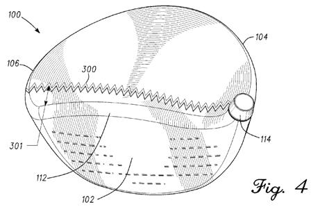
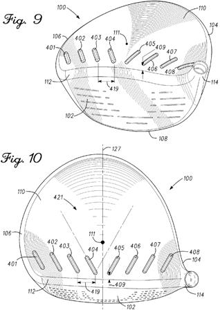
[0031] An example of a turbulator 300 is shown in FIG. 4. The turbulator 300 energizes the boundary layer on the crown 110 by generating turbulence in the boundary layer. The turbulator 300 is located on the crown 110 at a constant or variable distance 301 downstream of the leading edge 112 and may extend from the hosel 114 or the heel end 104 to the toe and 106. The turbulator 300 provides a plurality of projected surfaces in discrete or continuous form on the surface of the crown 110 at a height (not showing FIGS. 4-8, but generally shown with reference number 201 in FIG. 3). When the air flowing over the crown 110 encounters the projected surfaces of the turbulator 300, the air trips and becomes turbulent inside the boundary layer to energize the boundary layer.
.
.
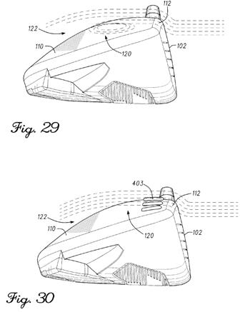
.[0057] FIG. 29 shows a schematic view based on actual airflow visualization experiments of airflow over the club head 100 without turbulators, and FIG. 30 shows a schematic view based on actual airflow visualization experiments of airflow over the same club head with the turbulators 400. In FIG. 29, the streamlines representing airflow approach the club had 100 and are diverted over the club face toward the leading edge. The streamlines traverse over the leading edge 112 and flow over the crown 110. However, the airflow becomes detached from the crown 110 at the separation region 120, and creates a turbulent wake 122 over a substantial section of the crown 110. This turbulent wake 122 increases the drag thereby reducing the speed of the club head 100. Referring to FIG. 30, the ridges 401-408 are positioned downstream of the leading edge 112 and upstream of the separation region 120 of FIG. 29. Accordingly, the flow remains attached on a substantial portion of the crown 110 as is shown by the streamlines in FIG. 30. Therefore, the separation region 120 is moved farther aft on the crown 110.
.
.
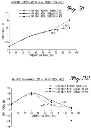
.[0063] As shown in Table 1, when the club head 100 has an orientation angle of greater than 60.degree., the aerodynamic drag force on the club head 100 is reduced for the club head 100 having the turbulator 300 or the turbulators 400. The reduction in drag is much greater for an orientation angle of 90 degrees. Referring to FIG. 31, which is a graphical representation of the data in Table 1, the noted reduction in drag for orientation angles of greater than 60 degrees is visually shown. Furthermore, the turbulator 400 (including one or more ridges 401-408) is shown to reduce the drag force on the club head 100 more than the turbulator 300.
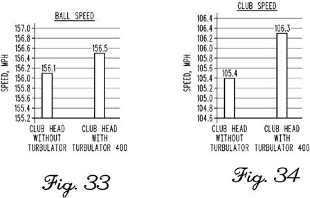
[0064] Table 2 shows measured values of lift expressed in lbs for different orientation angles of the club head. When the club head 100 has an orientation angle of greater than 60 degrees, the lift generated by the club head does not drop as sharply for the club head 100 having the turbulator 300 or the turbulators 400 as compared to the club head 100 without any turbulators. Referring to FIG. 32, which is a graphical representation of the data in Table 2, the noted drop in lift for the club head 100 without any turbulators is visually shown. The noted drop in lift is due to the higher pressure differential caused by the earlier boundary layer separation on the crown for the club head 100 without any turbulators as compared to the club head 100 having turbulator 300 or turbulators 400. Thus, Tables 1 and 2 and FIGS. 31 and 32 illustrate the adverse effects of early boundary layer separation on the crown for a golf club head without any turbulators and the effects of delaying the boundary layer separation on drag forces exerted on a golf club head.[0065] FIGS. 33 and 34 graphically show measured ball speed and club head speed for a golf club head without any turbulators and a golf club head having the turbulators 400. FIG. 33 shows that ball speed is higher when the golf club head includes the turbulators 400. This increase in ball speed is due to the higher club head speed as shown in FIG. 34 due to the turbulators 400 delaying boundary layer separation on the crown, thereby reducing drag forces on the club head.
While I wouldn’t even notice the turbulators, I wonder what PING purists would say.