
Nike is Definitely Thinking Outside the Box With This Design
If you frequent this site then you know that in the past six months I have authored several posts (HERE, HERE, and HERE) regarding some pretty cool, albeit unconventional, designs by Nike. Well, this week another Nike patent application became publicly available and it gives us a look at another interesting design that they have come up with. The patent application published as US Pub. No. 20100062874 titled “Golf Club Head and Golf Club with Tension Element and Tensioning Member,” and explains:
The following drawings tell the rest of the story.
Interesting concept, but this is design that I would have to see to believe.
Dave Dawsey - Monitoring Golf Patent Applications
SUMMARY
[0006] The principles of the invention may be used to provide a golf club and golf club head with a tension element and tensioning member for securing club head components together. In accordance with a first aspect, a golf club head includes a club head having a plurality of components and a plurality of retaining members, with each retaining member positioned on one of the components. A tensioning assembly for releasably securing the components of the club head together includes a tension element coupled to the club head components by way of the retaining members, and a tensioning member for introducing tension into the tension element.
[0007] In accordance with another aspect, a golf club head includes a face plate including at least one face plate retaining member, a body member having at least one body retaining member; and a tensioning assembly having a tension element and a tensioning member connected to the tension element. The tension element engages the face plate and body member retaining members to releasably secure the face plate to the body member.
[0008] In accordance with a further aspect, a golf club assembly includes a shaft having a first end and a second end; and a club head secured to the first end of the shaft. The club head includes a plurality of components and a plurality of retaining members, each retaining member being positioned on one of the components. A tensioning assembly releasably secures the components of the club head together and includes a tension element slidably attached to at least some of the club head components by way of the retaining members, and a tensioning member for introducing tension into the tension element.
[0009] Substantial advantage is achieved by providing a golf club and golf club head with a tension element and tensioning member for securing club head components together. In particular, certain embodiments allow a user or other individual to quickly and reliably secure the components of a club head together, along with the ability to disassemble the club head at a later time to replace or change one or more components of the club head.
[0010] These and additional features and advantages disclosed here will be further understood from the following detailed disclosure of certain embodiments.
.
.
.
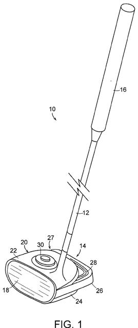
[0026] Club head 14 includes a plurality of components. As illustrated, this example golf club head 14 includes a face plate 18 and a body member 20 positioned behind face plate 18. In the illustrated embodiment, body member 20 includes a crown portion 22, a sole portion 24, and a skirt 26 positioned (e.g., extending) rearwardly from crown portion 22 and sole portion 24. It is to be appreciated that club head 14 may include any number of components.
.
.
.
[0028] The component elements of club head 14 are releasably secured to one another with a tensioning assembly 27 that includes a tension element 28 and a tensioning member 30. The use of tensioning assembly 27 allows a user or other individual to quickly and easily assemble the component parts of golf club head 14. Thus, for example, a user could be fitted in a shop for a golf club head that is optimized for their swing, and have that club assembled while in the shop. Once the user's swing has been evaluated and the desired components of the club head have been selected, the use of tensioning assembly 27 allows the components of club head 14 to be quickly assembled and releasably secured together.
[0029] Advantageously, the use of tensioning assembly 27 allows club head 14 to be disassembled at some future time, which allows for additional components to be added to club head 14, such as weights, for example, or for select components of club head 14 to be replaced with other components. Thus, it is possible to perform routine maintenance on a club head 14; as components of club head 14 experience fatigue or other performance degradation they can be quickly and easily replaced with other components.
[0030] As seen more clearly in FIG. 2, tension element 28 connects face plate 18 to body member 20. Tension element 28 has the ability to provide tension, which allows the components of club head 14 to be releasably and securely fastened to one another. Tension element 28 may take many forms including, but not limited to, a cable, cord, rope, wire, fiber, ribbon, chain, filament, and the like.
[0031] Tension element 28 engages (e.g., extends through, or is laced through) retaining members provided on the various components of club head 14. In the illustrated element, the face plate retaining members on face plate 18 are a pair of hooks 32, which are provided on a rear surface of face plate 18, as seen more clearly in FIG. 3. As illustrated here, hooks 32 are curved or arcuate members extending outwardly from the rear surface of face plate 18. Hooks 32 may be of unitary, that is, one-piece construction with face plate 18, or they may be separate elements secured to face plate 18 with any suitable fastening means such as welding, adhesive or the like.
[0032] It is to be appreciated that the retaining members need not be hooks, and can take any desired shape or form. For example, the retaining members could be L-shaped projections or J-shaped projections extending from face plate 18 or any other component of club head 14. The retaining members serve to slidably attach tension element 28 to club head 14. That is, the retaining members allow tension element 28 and the components of club head 14 to slide with respect to one another. At the same time the tension element 28 serves to releasably secure the components of club head 14 to one another.
[0033] Body member 20 may also include body retaining members to receive tension element 28. The body retaining members need not be the same shape as those found on face plate 18. A body retaining member provided on skirt 26 takes on another shape, namely a channel 34. Tension element 28 extends across sole portion 24 of body member 20 and then passes through channel 34 formed in an upper surface of skirt 26. Thus, it is to be appreciated that the retaining members that contact and retain tension element 28 with respect to the various components of club head 14 can take any desired shape or form that allows tension element 28 to connect and secure the various components of club head 14 to one another.
[0034] In this illustrative embodiment, tension element is not directly connected to crown portion 22 or sole portion 24 of body member 20; crown portion 22 and sole portion 24 are sandwiched between face plate 18 and skirt 26. It is to be appreciated that in other embodiments, tension member may be in direct contact with crown portion 22 and sole portion 24. For example, as seen in FIG. 4, crown portion 22 and sole portion 24 of body member 20 may include retaining members such as hooks 36 or any other retaining member. Thus, it is to be appreciated that tension element 28 need not contact each and every element of club head 14 directly in order to releasably secure all of the components of club head 14 together.
[0035] In the embodiment illustrated in FIG. 2, tension element is not directly retained by any element on sole portion 24, as noted above. In such an embodiment, crown portion 22 and sole portion 24 are connected to one another as a unit, which unit is then sandwiched between face plate 18 and skirt 26. Sole portion 24 and crown portion 22 may be connected to one another in any desired manner. For example, as illustrated in FIG. 5, a projection 38 may be formed about a peripheral edge of sole portion 24, and a mating recess 40 may be formed in a peripheral edge of crown portion 22, with projection 38 being received in recess 40. Thus, sole portion 24 and crown portion 22 are releasably connected or secured to one another in interlocking fashion. It is to be appreciated that in other embodiments a projection could be formed about the peripheral edge of crown portion 22 with the mating recess being formed about the peripheral edge of sole portion 24.
[0036] As noted above, tensioning member 30 serves to provide tension in tension element 28, thereby reliably and securely fastening the components of club head 14 to one another. In the illustrated embodiment, tensioning member 30, as seen in FIG. 6 in an engaged condition, is a ratcheting assembly 42 which operates in known fashion to tighten tension element 28, thereby firmly securing the components of club head 14 to one another.
[0037] Ratcheting assembly 42 includes a base portion 44 within which a spool 45 and ratcheting mechanism (not shown) is positioned. In the engaged condition of ratcheting assembly 42 shown in FIG. 6, the ends of tension element 28 are wrapped about spool 45 in known fashion as knob 46 is rotated by the user (clockwise in the direction of arrow A in the illustrated embodiment). As knob 46 rotates, the ends of tension element 28 move in the direction of arrows B into ratcheting assembly 42 and the opposed ends of tension element 28 are wound about spool 45, thereby shortening the portion of tension element 28 outside ratcheting assembly 42 and, consequently, increasing the tension in tension element 28 and securing the elements of club head 14 to one another.
[0038] To release the tension in ratcheting assembly 42, as illustrated in FIG. 7, knob 46 is lifted upwardly in the direction of arrow C to the disengaged condition, which releases the engagement of the ratcheting mechanism in ratcheting assembly 42, allowing the ends of tension element 28 to spin off of spool 45 and move outwardly from ratcheting assembly 42 in the direction of arrows D, thereby releasing the tension in tension element 28 and allowing club head 14 to be disassembled. A more detailed discussion of the internal operation of exemplary ratcheting assemblies is found in U.S. Pat. Nos. 5,934,599; 6,202,953; and 6,289,558, the entire disclosures of which are incorporated herein by reference in their entireties.
.
.
.
[0043] In certain embodiments, additional components can be added to club head 14. For example, as illustrated in FIG. 10, an additional weight 60 can be releasably secured to the other components of club head 14 by way of tension element 28. In the illustrated embodiment, club head 14 is shown without skirt 16 and with weight 60 positioned along the rear surface of body member 20, with tension element 28 engaged by retaining members 62 on weight 60. It is to be appreciated that weight 60 can be positioned at any location on club head 14, including being positioned within the interior of body member 20.
[0044] It is also to be appreciated that more than one weight 60 can be secured to club head 14. For example, as illustrated in FIG. 11, three weights 60 are positioned along the rear surface of club head 14. Any number of weights 60 can be included in club head 14, and each weight 60 can be positioned at any desired location within club head 14.
[0045] Since club head 14 can be quickly and easily assembled and disassembled through the use of tensioning assembly 27, the component parts of club head 14 can be quickly and easily interchanged or replaced with other components. Accordingly, a user can have a variety of different club head components that can be substituted for one another for a variety of reasons.
[0046] For example, a club component can be selected based on playing conditions expected to be encountered (e.g., different course conditions, different weather conditions, different wind conditions, etc.), the type of golf ball being used, and the skill or ability of the golfer. As a user improves, they may adapt a different playing style, and being able to replace the club head component allows them to modify their club without purchasing an entirely new club. It is to be appreciated that all aspects of the geometry or mass properties of club head 14 can be modified through the use of the interchangeable club head components including, but not limited to, the club head's shape, weight, weight distribution, bounce angle, center of gravity, moment of inertia, material of which it is formed, and appearance, which can alter the center of gravity, moment of inertia, and/or other "feel" characteristics of club head 14.
[0047] As noted above, tensioning member 30 can be positioned at any location within golf club 10. In certain embodiments, as illustrated in FIG. 12, tensioning member 30 is positioned at a second end of shaft 12, remote from club head 14. In this embodiment, tension element 28 engages (e.g., is wound or laced through) the components of club head 14 and then extends upwardly through shaft 12 to tensioning member 30 at the end of shaft 12.
The following drawings tell the rest of the story.


Dave Dawsey - Monitoring Golf Patent Applications
Posted by David Dawsey PE Esq at 3/15/2010 12:00 AM 
Categories: Litigation, Woods, Published Patent App of the Week, Balls
Categories: Litigation, Woods, Published Patent App of the Week, Balls
Comments