ZERO… The Odds of This Club Becoming a PING Product
Have you been itching for a driver with a small face and an unusual shape? If not, I suspect you are in good company (meaning about 99.9% of golfers). Although, I suspect most of us could adapt if it meant gaining 15+ yards off the tee.
Since I don’t anticipate such gains associated with reduced aerodynamic drag alone, I would be amazed if this design ever found its way into the PING product line; which doesn’t mean that I wouldn’t be the first in line to give such a wild design a swing at the next demo day. How many yards would you have to gain to game this beauty?
The patent application, which published last week, explains:
BACKGROUND
[0003] Golf club manufacturers have designed golf club heads with aerodynamic features to improve the flow of air over and around the golf club head. When air flows around a golf club head during a swing of a golf club, a wake, or an area of disturbed air flow, is formed behind the golf club head. In many cases, the wake creates a drag force on the golf club head, thereby slowing the speed of the golf club head throughout the swing. Thus, some golf club heads can be designed to lessen the disturbed air flow during the swing. In many cases, driver golf club heads are designed to maximize the moment of inertia (MOI) of the club head and maintain low and back center of gravity (CG) positions. Increased MOI can result in increased forgiveness for off center impact of a golf ball. Increased MOI can be achieved by maximizing the volume of the club head, and distributing the mass about the perimeter of the club head. Large volume club heads typically result in large club faces. The face of a golf club head is generally the biggest contributor to the drag forces on the club head during a swing. Large club head faces can result in higher drag forces, decreased swing speeds, and shorter ball distance. Therefore, there is a need in the art for a golf club head having a smaller face to reduce aerodynamic drag, while maintaining a high MOI and a low and back CG position.
.
.
.
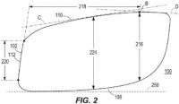
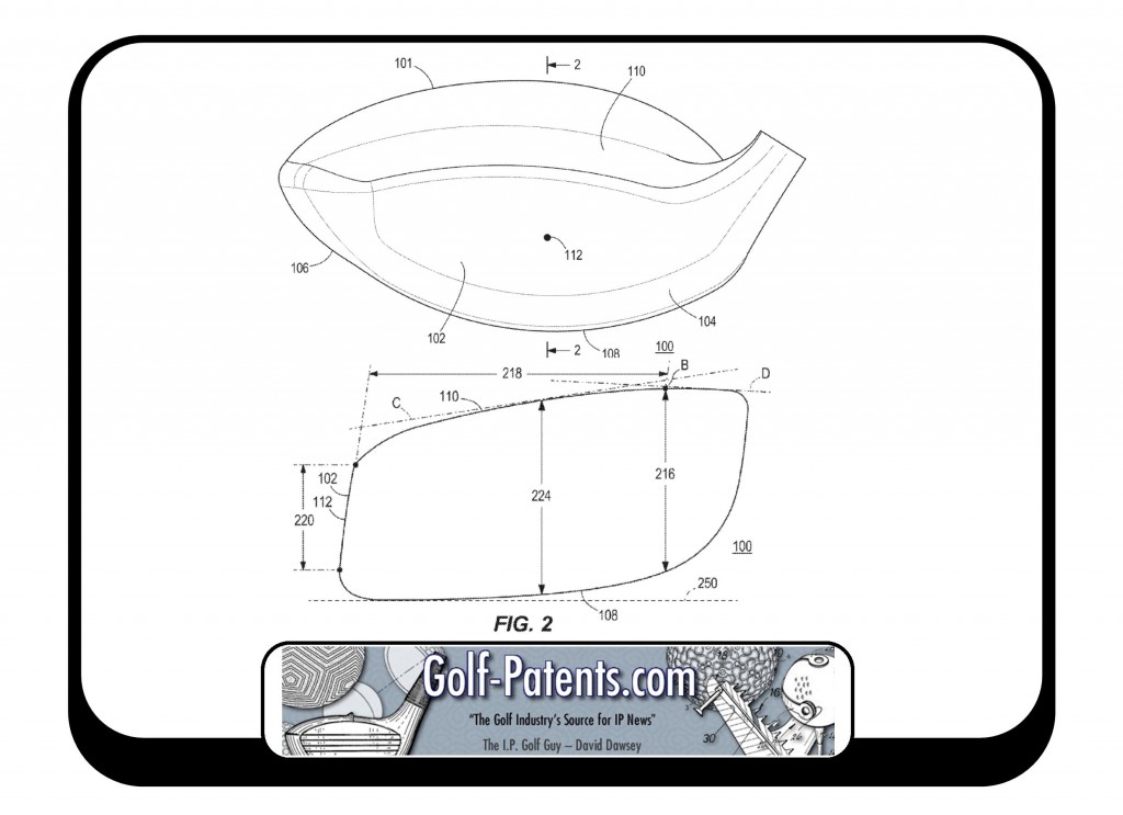
[0038] FIG. 2 illustrates a cross-sectional view of golf club head 100 across the cross-sectional line 2-2 of FIG. 1. Faceplate 102 has a faceplate height 220 measured perpendicularly to a ground plane 250 when golf club head 100 is at an address position. Faceplate height 220 is less than a faceplate height of a faceplate of a typical driver golf club head. In many embodiments, faceplate height 220 can be approximately 2.5 centimeters (cm) to approximately 3.1 cm. In some embodiments, faceplate height 220 can be approximately 2.5 cm, 2.6 cm, 2.7 cm, 2.8, cm, 2.9 cm, 3.0 cm, 3.1 cm. In some embodiments, faceplate height can be approximately 2.949 cm.
[0039] In some embodiments, crown 110 comprises a single inflection point B. Inflection point B is located at an inflection distance 218 from the faceplate 102, the inflection distance 218 measured from a center of the faceplate 102 and perpendicularly to a loft plane 120 positioned tangent to the center of the faceplate. The inflection point is a point on the external curve of crown 110 at which the sign of the curvature changes. As explained later, body 101 can have a body height 216 at single inflection point B. The surface of body 101 can transition somewhat linearly between the reference points for faceplate height 220, body height 216, and/or inflection distance 218, or the surface may transition with a curved profile between these points. Similarly, the surface of body 101 can transition somewhat linearly or with a curved profile through the reference points for strikeface width 330 (FIG. 3), and/or body width 332 (FIG. 3). In many embodiments, the surface area of the transition of the surface of body 101 can be larger than the surface area of the transition of the surface of the body of the typical driver golf club head. In many embodiments, the smaller area of faceplate 102 and larger transition surfaces result in decreased pressure drag on golf club head 100. This decreased pressure can result in increased swing speed and greater ball distance.
Let’s look at some data!
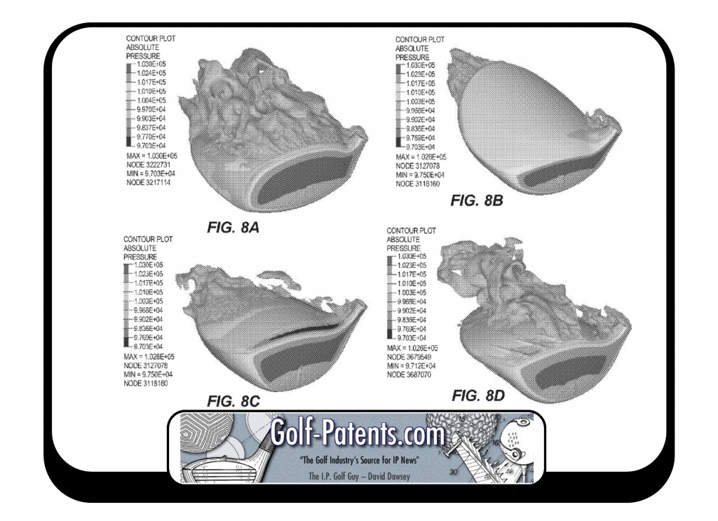
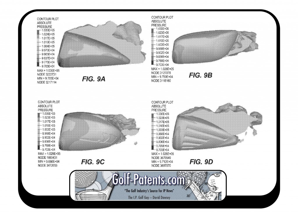
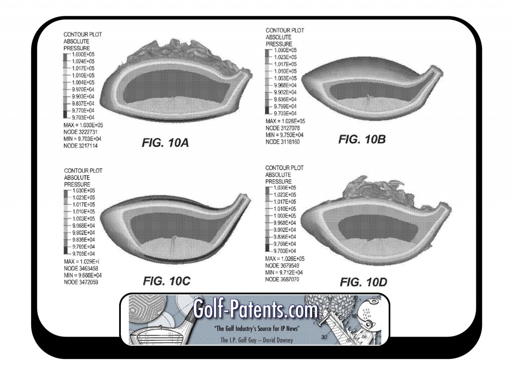
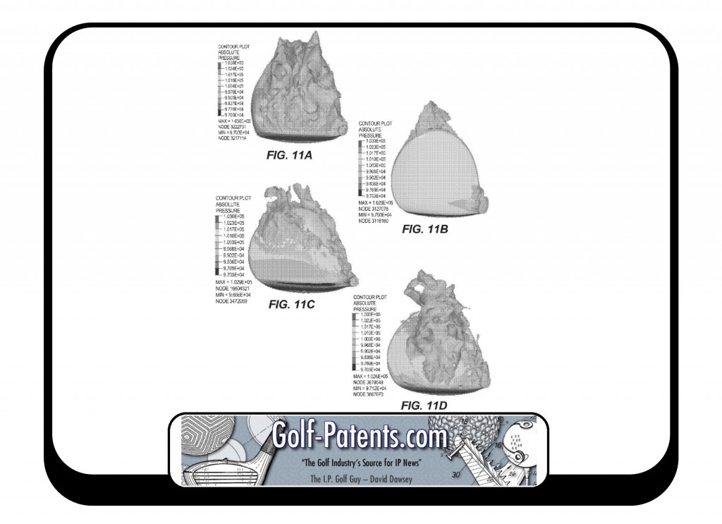
[0063] FIGS. 8-11 illustrate the reduced drag on golf club head 400 (FIGS. 4-6) compared to typical golf club heads using computational fluid dynamics. Golf club head 400 is represented in FIGS. 8B, 9B, 10B, and 11B. The remaining golf club heads in FIGS. 8-11 (i.e. FIGS. 8A, 8C, 8D, 9A, 9C, 9D, 10A, 10C, 10D, 11A, 11C, and 11D) represent typical golf club heads. For example, FIGS. 8A, 9A, 10A, and 11A illustrate a typical golf club head having a greater faceplate height and a greater faceplate area than the height and area of faceplate 402 of golf club head 400, respectively. Further, the typical golf club head illustrated in FIGS. 8A, 9A, 10A, and 11A has an inflection distance less than approximately 2.5 cm (i.e. less than the inflection distance 418 of golf club head 400). For further example, FIGS. 8C, 8D, 9C, 9D, 10C, and 10D illustrate typical golf club heads having a greater faceplate height and a greater faceplate area than the height and area of faceplate 402 of golf club head 400, respectively. Further, the typical golf club heads illustrated in FIGS. 8C, 8D, 9C, 9D, 10C, and 10D have an inflection distance less than approximately 7.5 cm (i.e. less than the inflection distance 418 of golf club head 400).
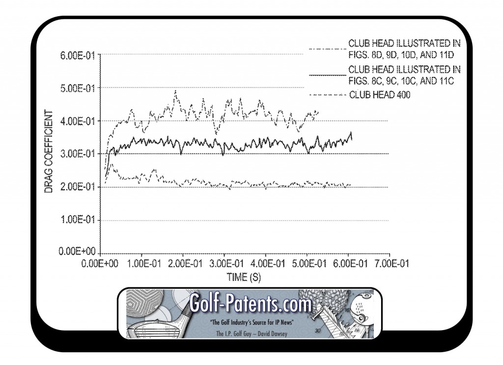
[0064] Further referring to FIGS. 8-11, the golf club head 400 (FIGS. 8B, 9B, 10B, and 11B) has reduced flow separation on the crown, and reduced pressure on the faceplate during a swing (due to the reduced faceplate height and surface area), resulting in reduced drag coefficient on the club head 400 compared to typical golf club heads.
[0065] FIG. 12 graphically illustrates the reduced drag coefficient of golf club head 400 compared to the typical golf club head illustrated in FIGS. 8C, 9C, 10C, and 11C, and the typical golf club head illustrated in FIGS. 9D, 9D, 10D, and 11D, according to the computational fluid dymanic simulations visually illustrated in FIGS. 8-11.
[0066] From FIGS. 8-12, it can be seen that the flow separation is greater on the crown of the typical golf club heads, and the flow separation is reduced on golf club head 400. In FIGS. 8-11, the air flow separates closer to the faceplate on the typical driver golf club heads and stays attached to the body of the typical driver golf club heads for a longer length over the crown. This early separation causes an increase in turbulence over the crown of the typical driver golf club heads, thereby increasing drag on the typical driver golf club heads. The smaller area of faceplate 402 on golf club head 400 and the longer transition of body 401 (the longer inflection distance 418) provide a more streamlined golf club head, which results in a delay in flow separation and a decrease in pressure or drag forces on crown 408. Golf club head 100 (FIGS. 1-3) has similar advantages to golf club head 400 (FIGS. 4-6).
Wow, that is a pretty small faceplate height. While it may not intimidate a Tour player, it would scare the heck out of me.
Dave Dawsey – The Golf Invention Attorney
PS – follow me on Twitter (@GolfPatents) and sign-up HERE to receive posts via email.
PPS – If you like what we are doing, please considering helping us out and make your online gear purchases through our Amazon affiliate link. Every little purchase helps us keep the site up and running! Thanks.

