Stealth Grooves… Just What Golfers Have Been Looking For
Recently an interesting groove patent application published, which led to me to an even more fascinating “stealth groove” patent. The patent application belongs to Performax Golf and Composite, Inc. and is titled “Golf Club Head Having Score Line Structure” (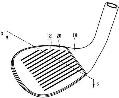
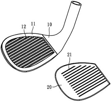
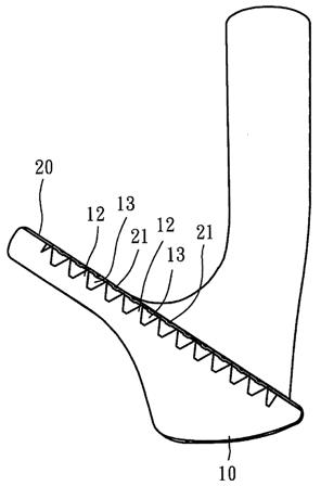
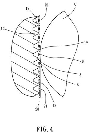
[0015] The club head body 10 has a recessed portion 11 thereof, a plurality of supporting ribs 12 and a plurality of internal grooves 13 alternatively arranged in parallel in the recessed portion 11 and extending in the transverse direction, i.e., the toe-and-heel direction. It is to be understood that the toe-and-heel direction of the supporting ribs 12 and the internal grooves 13 is not a limitation. In an alternate form of the present invention, as shown in FIG. 5, the supporting ribs 12 and the internal grooves 13 extend in the longitudinal direction. Further, the distance between each two adjacent supporting ribs 12 can be the same. Alternatively, the distance between each two adjacent supporting ribs 12 can be different.
[0016] The ball-striking face plate 20 can be prepared from ceramics, stainless steel, maraging steel or titanium alloy. The ball-striking face plate 20 has a plurality of external score lines 21 arranged in parallel on the front face thereof in a predetermined direction. The external score lines 21 can be arranged to extend in the transverse direction, longitudinal direction, or any of a variety of other directions. According to the present preferred embodiment, the external score lines 21 are arranged to extend in the transverse direction. The ball-striking face plate 20 is fixedly mounted in the recessed portion 11 of the club head body 10 in such a manner that the back wall of the ball-striking face plate 20 is stopped against the topmost edges of the supporting ribs 12 and the external score lines 21 are respectively suspending above the internal grooves 13 between each two adjacent supporting ribs 12. Thus, the part of the ball-striking face plate 20 that is supported on the supporting ribs 12 is not deformable, and the other part of the ball-striking face plate 20 that is not supported on the supporting ribs 12 is deformable. The ball-striking face plate 20 can be fastened to the club head body 10 fixedly by fusion welding, brazing, scarf joint or glue-bonding, or two or three of the aforesaid techniques at the same time.
[0017] According to the aforesaid structure, as shown in FIG. 4, the ball-striking face plate 20 has the external score lines 21 arranged on the front face thereof, like the arrangement of the face plate of a conventional golf club head, to enhance friction between the ball-striking face plate 20 and the ball. However, when hitting the ball (referenced by C), the part of the ball-striking face plate 20 that is not supported on the supporting ribs 12 will be temporarily deformed to get the ball control. Further, the pressure applied by the player to the club head body 10 is transferred through the supporting ribs 12 to the ball-striking face plate 20, and the ball-striking face plate 20 causes the ball to spin backwards by means of the external score lines 21. The point of force application A of the supporting ribs 12 at the ball-striking face plate 20 and the contact point B between the external score lines 21 and the ball are different and not overlapped, therefore a torque is produced between the point of force application A and the contact point B during the time period the ball-striking face plate 20 is caused to deform and then returns to its former shape, thereby increasing the back spin amount. In a test where a mechanical arm was operated to strike the ball with a machine made according to the present invention at a speed of 75 mph, the test result shows a back spin amount 8000 rpm, a carry distance 155 yards, and a rolling distance 3 yards. Subject to the aforesaid test, the structure of the present invention provides better ball control when compared to conventional golf club head designs that have only one layer of score lines on the face. This characteristic satisfies the requirement for precision ball control.
The application mentions a patent that may get your attention simply by the inclusion of “stealth grooves” in the title. The application explains:
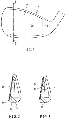
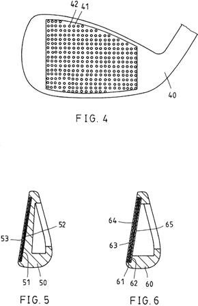
[0006] U.S. Pat. No. 6,368,231 discloses an improved golf club head design, entitled “Stealth grooves of ball-striking face of golf club head“. This design discloses a hidden grooves concept for allowing deformation of the ball-striking face plate to increase the standing time of the ball on the ball-striking face plate. However, the ball-striking face plate does not provide any means to match the hidden grooves structure for enabling the return force to be utilized to enhance the friction between the ball-striking face plate and the ball for a better ball control.
Check out these “stealth grooves” from USPN 