Sir, Would You Like Your Golf Ball Coated with Aluminum, Steel, Tungsten, Titanium, Magnesium, or an Iron Alloy? Would You Prefer Coated Dimples or Lands?
Why thank you kind salesperson, I would like my golf balls coated with magnesium (I love the sparks), and only lightly on the land areas, as I lose too much distance when my dimples get filled. Can’t you just imagine that exchange occurring in the golf ball section of GolfGalaxy? It may be a reality some day, particularly if Nike brings the following golf ball invention to market.
Continuing with their pursuit of acquiring golf ball intellectual property, last week Nike had an interesting golf ball patent application publish as US Pub. No. 20110177885 titled “Golf Ball Having Increased Moment of Inertia,” which describes the invention as:
Generally disclosed is a golf ball having a core and a cover layer. The cover layer includes a coating material thereon that increases the golf ball’s moment of inertia. The coating material is coated on the cover layer in a pattern corresponding to one of the dimple pattern and the pattern of land areas separating the dimples. The golf ball’s moment of inertia is increased while utilizing only a small amount of the coating material as a result of the pattern of coating material, which locates the coating material at an outermost radial distance from the golf ball’s center of rotation (i.e., the golf ball’s center of gravity). The increased moment of inertia causes the golf ball to have a lower rate of spin when hit by a golf club, thereby displaying different play characteristics.
The application goes on to explain:
[0001] The present invention relates generally to a golf ball, and a method of manufacturing the golf ball. In particular, a cover layer on the golf ball includes coated areas such that the golf achieves an increased moment of inertia.
[0002] The game of golf is an increasingly popular sport at both the amateur and professional levels. A wide range of technologies related to the manufacture and design of golf balls are known in the art. Such technologies have resulted in golf balls with a variety of play characteristics. For example, different golf balls are manufactured and marketed to players having different golfing abilities, such as different swing speeds.
[0003] Accordingly, a golfer may use different golf balls having different play characteristics depending on the golfer’s preferences. For example, different dimple patterns may affect the aerodynamic properties of the golf ball during flight, a difference in the cover hardness may affect the rate of backspin, or a difference in the moment of inertia may also affect the rate of backspin. With regard to the moment of inertia in particular, a golfer may choose to use a golf ball having a higher moment of inertia or a lower moment of inertia. A higher moment of inertia will generally result in a lower rate of spin by the golf ball during flight after being struck by a golf club face, while a lower moment of inertia will generally result in a higher rate of spin by the golf ball. Higher rates of spin are generally associated with better controllability, while lower rates of spin are generally associated with increased distance off the tee.
[0004] A wide range of golf balls having a variety of moment of inertia characteristics are known in the art. Generally, the moment of inertia of a golf ball is determined by the composition and physical arrangement of the various layers making up the golf ball. Accordingly, a number of different golf ball materials are mixed and matched in various combinations and arrangements to create golf balls having different moments of inertia.
[0005] However, designing golf balls to achieve desired moment of inertia characteristics suffers from at least several difficulties. Known golf balls generally use heavy additives interspersed in a polymer matrix comprising one or more outer layers of the golf ball, such that the heavy additive adds weight to an outer radius of the golf ball, in order to increase the golf ball’s moment of inertia. However, generally, the construction of known golf balls requires that a wide range of design variables such as layer arrangement, materials used in each layer, and layer thickness be balanced against each other. Changes to any of these variables may therefore achieve a desired moment of inertia only at the expense of other play characteristics. Additionally, materials costs and design costs associated with known golf ball constructions may unduly increase the cost of the golf ball to the end consumer.
.
.
.
[0021] Generally, the present disclosure relates to a golf ball having an increased moment of inertia. The increased moment of inertia is achieved by coating a dense material onto the cover layer in a selected pattern. The pattern may correspond to the plurality of dimples, or the pattern may correspond to at least one land area separating at least two dimples. Coating the dense material in a selected pattern increases the golf ball’s moment of inertia while also affording the golf ball other advantageous physical properties, such as a desirable hardness pattern. In one embodiment, coating the dense material in a pattern corresponding to at least one land area separating at least two dimples results in an increased moment of inertia while using minimal dense material due to the dense material being added at the farthest radial distance from the golf ball’s center of gravity.[0022] This disclosure further relates to methods of manufacturing such a golf ball.
[0023] The moment of inertia of a body is a measure of an object’s resistance to changes in its rotation rate. Generally, when a body having a high moment of inertia is imparted with a certain rotational energy, the body will rotate at a rate that is slower than the rate at which a body having a low moment of inertia will rotate when imparted with the same amount of rotational energy. The moment of inertia of a spinning body is generally defined as the integral of r^2*dm, where r is the radial distance to the axis of rotation and dm is the differential of the mass at that radius r. Moment of inertia has units of mass times distance squared, for example in SI units: kg*m^2. The moment of inertia of a uniform solid sphere is given by the equation (2/5)*mass*radius^2. However, a golf ball is not uniform, but instead varies in density among its several layers. The present disclosure changes the rotational performance characteristics of a golf ball by coating a dense material on an outermost layer of the golf ball in a selected pattern.
.
.
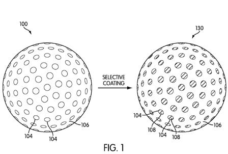
.[0026] In the embodiment shown in FIG. 1, golf ball 100 undergoes selective coating so as to be changed into golf ball 130. The selective coating process itself is discussed in greater detail below. By the selective coating process, a coating material 108 is selectively applied on the first pattern (corresponding to the dimples 104). Although FIG. 6 shows the entirety of the first pattern (i.e., all of the dimples) being coated with coating material 108, coating material 108 may alternatively coat only a portion of the first pattern. Generally, in this embodiment, coating material 108 may overlap at least a portion of the first pattern, but does not substantially overlap the second pattern.
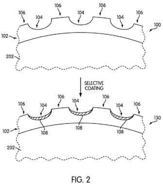
[0027] FIG. 2 shows a cross-sectional view of the dimples 104 and land areas 106 shown in FIG. 1. In FIG. 1, coating material 108 is coated on top of each of the dimples 104, forming a thin layer of coating material 108 on a cover layer 102. Generally, cover layer 102 substantially surrounds a core 202, and includes the dimples 104 and land areas 106 thereon. Although core 202 is shown to be in direct contact with cover layer 102 in FIG. 2, the golf ball 100 or 130 may include one or more intermediate layers between core 202 and cover layer 102 as may be desired and as are
known in the art of golf ball construction.[0028] The thickness of coating material 108 may generally be any thickness that fits within a dimple. Coating material 108 should generally not be so thick as to significantly affect the aerodynamics of the golf ball, however coating material 108 may be applied in such a way as to achieve a desired dimple depth configuration. In certain embodiments, cover layer 102 may have a thickness of about 2 mm or less. A clear coating layer (not shown) on top of cover layer 102 may generally have a thickness of about 20 microns. Accordingly, in these embodiments, coating material 108 may have a thickness that is, for example, on the order of about 20 microns or less. Generally, coating material 108 may have a thickness of about 1 micron to about 20 microns (about 0.001 mm to about 0.02 mm), inclusive and taking into account manufacturing tolerances.
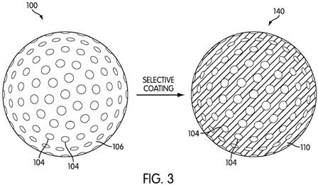
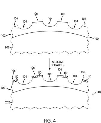
[0029] FIG. 3 shows a second embodiment, wherein land areas 106 of golf ball 100 are coated with a coating material 110 so as to produce golf ball 140. In this embodiment, coating material 110 covers the entirety of the second pattern (corresponding to the land areas), as shown. However, more generally, coating material 110 covers at least a part of the second pattern, and does not substantially overlap the first pattern. Coating material 110 may therefore overlap some portion less than the entirety of the second pattern, or the entirety of the second pattern, as may be desired.
[0030] FIG. 4 shows a cross-sectional view of the embodiment of FIG. 3. Specifically, land areas 106 on golf ball 100 are selectively coated with coating material 110 to form golf ball 140. As was discussed with respect to coating material 108, coating material 110 should generally not be so thick as to significantly affect the aerodynamics of the golf ball, however coating material 110 may be applied in such a way as to achieve a desired dimple depth configuration. Accordingly, coating material 110 may have a thickness that is, for example, on the order of about 20 microns or less. In one embodiment, coating material 110 has a thickness of between about 1 micron and about 20 microns, inclusive and taking into account manufacturing tolerances. Coating material 110 may have a thickness that is slightly smaller than a thickness of coating material 108 for an equivalent moment of inertia of the golf ball, because coating material 110 is applied at a further radial distance from the center of the golf ball 140.
.
.
.
[0036] The golf ball in accordance with the present disclosure achieves an increased moment of inertia due to the density of the coating material being higher than the density of the core. As shown in FIGS. 4-8, generally, core 202 of the golf ball 100 has a first density, and coating material 108 or coating material 110 has a second density, where the second density is higher than the first density. The coating material 108 or 110 therefore increases the moment of inertia of the golf ball 130 or 140, because more of the golf ball’s mass is located at an outer radial distance from the golf ball’s axis of rotation (the golf ball’s axis of rotation being the golf ball’s center of gravity).[0037] The coating material may generally be any material having a density that is greater than the density of the core. A wide range of polymers are known in the art that may be manufactured to have high density values. Generally, the polymer making up the coating material may be any thermoplastic, thermoset, ionomer, copolymer, or other polymer material known and used in the art of golf balls so long as the polymer has a density that is greater than the density of the core. The density of a polymer coating material may be determined in accordance with ASTM D792, for example, or in accordance with other known measurement standards.
[0038] Additionally, the coating material may be a metal plating. Nearly any typical metal may be used, as most metals have a density that is significantly higher than the polymer materials conventionally used to form golf ball cores. Exemplary metals that may be used as the coating material include aluminum, steel, tungsten, titanium, magnesium, and iron alloys, and mixtures thereof, among a variety of other metals. The metal coating material may be selected based on density, hardness, workability, and cost effectiveness, for example, among other selection criteria.
.
.
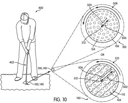
.[0044] A comparative illustration of golf ball 100 with golf ball 140 is shown in FIG. 10. A golfer 400 swings a golf club 402 toward a golf ball on a tee. If the golf ball on the tee is golf ball 100, then golf ball 100 will exhibit play characteristics as shown in the upper half of FIG. 10 upon being struck by golf club 402. Specifically, golf ball 100 will exhibit a high rate of rotation 508 around its center of gravity 512 because its moment of inertia, as graphically illustrated by the length 504 of moment arm 500, is relative low. On the other hand, golf ball 140 exhibits a lower rate of rotation 510 about the center of gravity 512 because its moment of inertia, as graphically illustrated by the length 506 of moment arm 502, is relatively high. Accordingly, golf ball 140 will display different play characteristics than golf ball 100, and so may be more desirable to certain golfers based on the golfers’ preferences.
What will they think of next? Oh, by the way this is post #1000! Crack the bubbly….
David Dawsey – Keeping an Eye on Golf Ball Coatings

