Place Your Bets, Will We See This Technology in a PING Driver?
As I have said before, PING drivers are known for their classic simple designs. Purists love the designs, but some would suggest they are old-school (ahem, not loaded with technology). Nonetheless, they always seem to perform, even without 10 different technology acronyms plastered to the product. That may soon change.
Today an interesting patent application owned by Karsten published as US Pub. No. 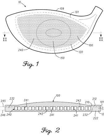
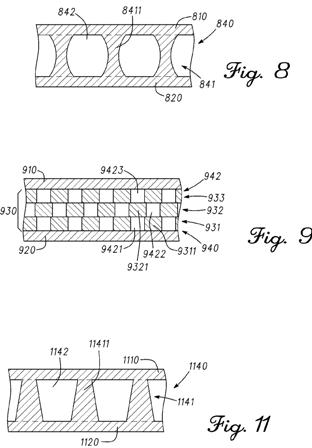
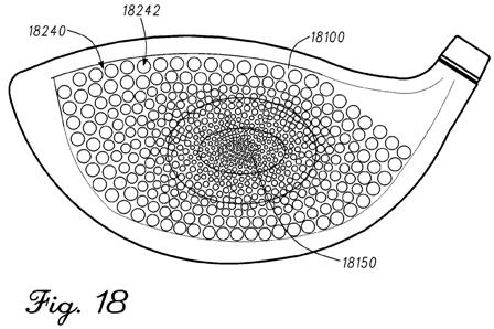
[0022] FIG. 18 presents a front “x-ray” perspective view of a faceplate comprising a cell lattice variable cell dimensions.
The application describes the invention as:
Embodiments of golf club face plates with internal cell lattices are presented herein. Other examples and related methods are also disclosed herein.
The application goes on to explain:
[0037] Turning to the drawings, FIG. 1 illustrates a front perspective view of golf club head 10 comprising face plate 100 coupled to club head body 109. FIG. 2 illustrates a cross-sectional view of face plate 100 cut along line II-II of FIG. 1. As can be seen in FIG. 2, face plate 100 comprises inner skin 210, outer skin 120, and midsection 230 between inner skin 210 and outer skin 120, where midsection 230 comprises cell lattice 240 having walls 241 defining cells 242. In the present example, cell lattice 240 extends from inner midsection end 245 (where cell lattice 240 is coupled to inner skin 210), to outer midsection end 246 (where cell lattice 240 is coupled to inner skin 210). Cell lattice 240 is thus fully encapsulated within faceplate 100 in the present example, between inner skin 120 and outer skin 210, and by perimeter midsection area 232. Although inner midsection end 245 and outer midsection end 246 are represented along dotted lines in FIG. 2, in the present embodiment the interface between midsection 230 and inner skin 210 or outer skin 120 may be seamless or imperceptible visually and/or structurally.
[0038] The different portions of faceplate 100 can comprise different thicknesses. In the present example, the thickness of outer skin 120 is approximately 0.03 inches (approximately 0.08 millimeters (mm); the thickness of midsection 230 is approximately 0.07 inches (approximately 1.78 mm); and the thickness of inner skin varies, being approximately 0.05 inches (approximately 0.13 mm) towards the center, and approximately 0.03 inches (approximately 0.08 mm) towards the perimeter. The thickness of inner skin 210 is greater than the thickness of outer skin 120 in the present example, where inner skin 210 faces away from the impact surface of faceplate 100, to better distribute impact stresses throughout the faceplate. In some examples, the thickness of inner skin 210 and outer skin 120 can be substantially similar to each other, and/or may not vary.
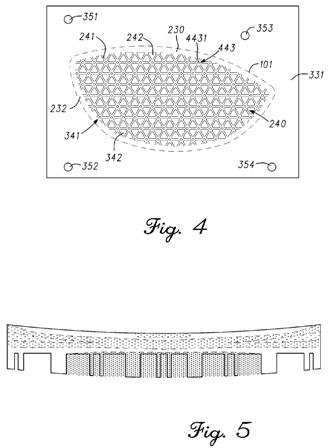
[0039] In the present example, face plate 100 is shown with inner skin 210, outer skin 120, and midsection 230 merged together into a single integral piece of material. In some examples, inner skin 210, outer skin 120, and/or midsection 230 may be merged together without using adhesives or fasteners, such as via a high-pressure and/or high-heat process. In the same or other examples, such process may comprise a diffusion bonding process. The ability to combine midsection 230 between inner skin 210 and outer skin 120 and into a single integral piece of material can provide many benefits, such as a reduction in the weight of face plate 100 via cell lattice 240. In some examples, encapsulating cell lattice 240 within face plate 100 can permit weight savings of approximately 8% to approximately 25%. Such results can be achieved without compromising the strength or durability of face plate 100, and without introducing detrimental bending, elastic and/or flexing susceptibilities that would result from uneven stress distribution if, for example, face plate 100 were made with cell lattice 240 exposed and/or without one of inner skin 210 or outer skin 120. As an example, and skipping ahead in the figures, FIG. 5 illustrates a cross-sectional view of a finite element analysis graphic showing uneven stress distribution detrimentally concentrated, as denoted by the heavily-dotted center region, in and around the void portions of an exposed cell lattice in an embodiment comprising only a single skin coupled to the cell lattice.
[0040] Backtracking to FIG. 3, a perspective view is illustrated of portions of different layers 300 comprising face plate 100 prior to being merged together, including midsection layers 330. In the present example, midsection 230 comprises midsection layers 330 merged together into the single integral piece of material of face plate 100. In the same or other examples, the plurality of midsection layers 330 can be merged together via the high-pressure and high-heat process described above. As can be seen in FIG. 3, inner skin 210 and outer skin 120 can also be formed out of several layers, such as outer skin layers 320 and inner skin layers 310, which may be merged together into the single integral piece of material of face plate 100. Although in the present embodiment inner skin 210 comprises more inner skin layers 310 than outer skin 120 comprises outer skin layers 320, there can be other embodiments where such relationship is inverse, or where both skins comprise the same number of layers. There may be other embodiments, however, where one or more of inner skin 210, outer skin 120, and/or midsection 230 may originally comprise a single layer, rather than a plurality of layers coupled together.
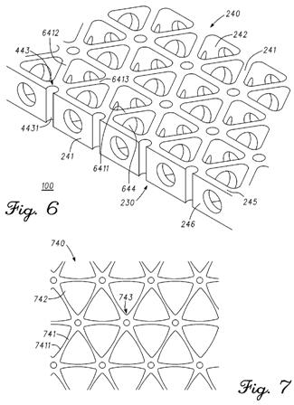
[0041] FIG. 3 shows portions of layers 300 as sheets of metallic material, and illustrate midsection layers 330 with representative cutouts configured to form cell lattice 240 when merged together. FIG. 4 illustrates a front view of midsection layer 331 of midsection 230, comprising lattice pattern 341 and alignment elements 351-354. Lattice pattern 341 comprises a plurality of cutouts, such as cutout 342, that define a layer portion of walls 241 and a layer portion of the volume of cells 242 of cell lattice 240. In some examples, cell lattice 240 may be formed by one or more processes, such as by machining and/or by chemically etching the cutouts of the different lattice patterns of midsection layers 330 prior to merging layers 300 (FIG. 3) together. In examples involving the machining of cell lattice 240 or one or more of its elements, such machining can be carried out via one or more techniques, such as through computer numerical control (CNC) machining, waterjet cutting, and/or electrical discharge machining.
Now the million dollar question, is this technically and economically
feasible or is it just another R&D project that will never see the light of day?
