Is Golf Ready for a “Thermoreactive Face”?
Guess which golf equipment company filed a patent application directed to a “thermoreactive face.” The answer is at the bottom of this post. The patent application published as US Pub. No. A ball striking device, such as a golf club, includes a head that includes a face having a ball striking surface configured for striking a ball and a body connected to the face and extending rearward from the face. The face has an area of highest response located proximate a center of the ball striking surface. The face is formed of a first material and a second material that forms at least a portion of the area of highest response. The second material has a thermal modulus response that is different from a thermal modulus response of the first material.
The application goes on to explain:
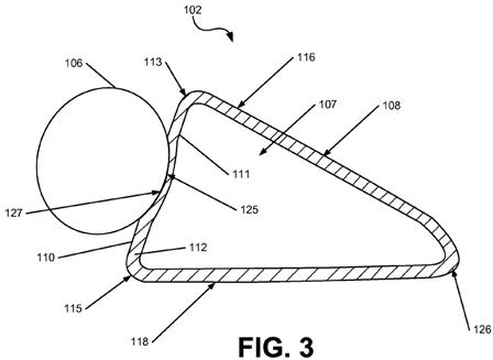
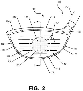
[0065] In general, FIGS. 1-3 illustrate a head 102 that has a face 112 that is at least partially formed of a material with a thermally variable modulus, meaning that the elastic modulus of the material changes based on temperature. An impact between the face 112 and the ball 106 generates an amount of heat, at least some of which is absorbed by the face 112, changing the temperature of the face 112 at least in an area proximate the impact. The material may have a thermally-variable modulus that causes the modulus to change to a significant degree due to the heat absorbed by the face 112 during impact. In one embodiment, the energy of an impact of a ball on the face 112 is between 10-100 Joules, and the resultant temperature rise of the face may be between 0.1 degrees C and 5 degrees C, depending on materials, swing speed, and other conditions. FIG. 2 schematically illustrates an impact zone 125 between the ball 106 and the face 112, which causes the face 112 to deform within the impact zone 125 and generates heat that is absorbed by the portions of the face 112 within the impact zone 125. It is understood that the impact zone 125 shown in FIGS. 2-3 corresponds to an impact at or around the area of highest response 127 of the face 112, which, in a driver-type club head 102, is typically at or around the geometric center of the face 112. FIG. 3 illustrates deformation of the face 112 caused by the impact. It is understood that the degree of deformation of the face 112 in FIG. 3 may be exaggerated for the purposes of showing detail. In one embodiment, the modulus of at least part of the area of the face 112 local to the impact zone 125 may change at least 10% due to heat and pressure generated by an impact of the ball 106 on the ball striking surface 110 at a particular swing speed during impact, as described below. In another embodiment, the modulus may change up to 50% at high swing speeds.
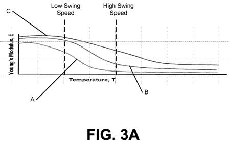
[0066] As one example, a material with a thermally variable modulus can produce an increased “trampoline” effect and increased response (i.e. energy and/or velocity transfer) during impact. In such an example, the heat that is generated during impact can reduce the modulus of the material in the impact zone 125 to make the local material more flexible, while the surrounding material remains relatively stiffer. This creates an impact structure similar to an edge-supported trampoline, having a flexible center suspended by a stiff perimeter, leading to increased trampoline effect and/or increased contact time, and thus increased energy transfer. FIG. 3 illustrates such an impact. In one embodiment, the heat generated by the ball 106 during impact may change the modulus of the areas of the face 112 local to the impact zone 125 so that the modulus is at least 10% different relative to areas of the face 112 that are spaced away from the impact zone 125. Additionally, the amount of modulus change can be customized to the swing speed of a golfer, because impacts at greater velocity produce more heat. For example, for a golfer with a lower swing speed, a material may be selected such that the modulus of the areas of the face 112 local to the impact is at least 10% lower than at ambient conditions (i.e. room temperature) due to heat generated at swing speeds of 90 to 130 ft/s. In another example, for a golfer with a higher swing speed, a material may be selected such that the modulus of the areas of the face 112 local to the impact is at least 20% lower due to heat generated at swing speeds of at least 155 ft/s or at least 160 ft/s. FIG. 3A illustrates how the moduli of several different materials change based on temperature (which is indicative of swing speed), and a material can be selected for a particular swing speed accordingly. Material A in FIG. 3A represents one example of a material that can utilize heat generated during impact to produce a flexible impact zone 125 and a stiff surrounding area, resulting in an increased trampoline effect at many different swing speeds. Further customization is possible.
[0067] As another example, a material with a thermally variable modulus can produce increased face flexibility at a wider range of swing speeds. For example, many golf clubs are designed based on performance at a typical professional golfer swing speed of 160 ft/s. The COR (coefficient of restitution) test is performed at this swing speed, and many existing club heads 102 offer optimal performance at or around this swing speed. However, the faces 112 of such club heads 102 may have less flexibility, and consequently less deformation and trampoline effect, at lower swing speeds. A material with a thermally variable modulus can be selected to provide a decreased modulus due to heat produced at a lower swing speeds such as 90 to 130 ft/s, allowing for more flexibility at such swing speeds. Additionally, the material may be selected to provide a decreased modulus at such lower swing speeds, with little to no further decrease in modulus at higher swing speeds, as seen in the graph in FIG. 3A. For example, a material may experience a decrease in modulus of at least 20% due to heat generated at lower swing speeds of 90 to 130 ft/s, while having a further change in modulus of no more than 5% at a higher swing speed of 160 ft/s. The material may also have a modulus at ambient conditions that is at least 20% greater than the modulus at the range of lower swing speeds. As similarly described above, FIG. 3A illustrates how the moduli of several different materials change based on temperature (which is indicative of swing speed), and a material can be selected for a particular swing speed accordingly. Materials A and B in FIG. 3A represent examples of materials with a thermally variable modulus that can be effective for lower swing speeds, and Material C in FIG. 3A represents one example of a material with a thermally variable modulus that can be effective for higher swing speeds. Further customization is possible.
[0068] Below are described several different general and specific embodiments for creating a face having a thermally variable modulus response in accordance with aspects of the present invention. Generally, such embodiments may utilize a single material having a selected
thermal modulus response, or multiple materials having different thermal modulus responses.[0069] In one embodiment, a head 102 as shown in FIGS. 2-3 may have a face 112 made of a single material that produces a thermal modulus response as described above, such as to produce increased trampoline effect at any swing speed, or to produce greater flexibility at a particular swing speed. Such a single-material face 112 can produce increased trampoline effect and/or greater flexibility around the impact zone 125 for impacts on nearly any portion of the face 112, and not only in the area of highest response 127 of the face 112. This single material of the face 112 can be a metal, ceramic, composite, or other material, including a layered composite material. A layered or laminate composite may contain a plurality of alternating layers of materials having different moduli, such as a titanium-carbon fiber composite layered structure (e.g. TiGr) or an aluminum-fiberglass composite layered structure (e.g. GLARE). Other layered structures are usable with the face 112, for example: titanium over an elastomer or carbon-fiber composite over a foam. Such composites need not be symmetrical. In another embodiment, the head 102 may include at least a portion that is formed of one or more different materials than the supporting structure of the face 112, which second material may be located at or around the area of highest response 127 of the face 112, or at another location. As shown in FIGS. 4-7 and discussed below, such different materials may be provided in the form of an insert connected to the face 112.
[0070] In one embodiment, the thermal modulus response of a material used in the face 112 may be affected by a molecular phase change in the material, due to heat generated during impact of a ball on the ball striking surface. In other words, the material may be formed in a first molecular phase at ambient conditions, and the heat generated by an impact of a ball 106 on the ball striking surface 110 may be sufficient to change the molecular phase of a material to a second molecular phase. The second molecular phase may have a different modulus and/or a different thermal modulus response than the first molecular phase. It is understood that the material may change back to the first molecular phase after impact, and that a molecular phase change of the material may be effected in part by the pressure resulting from an impact, in addition to the resulting heat.
[0071] At least a portion of the face 112 may be formed of such a phase-change material, and in one embodiment, at least a portion of the area of highest response 127 of the face 112 is formed of the phase-change material. Additionally, the phase-change material may be incorporated into an insert that is connected to the face 112, such as the inserts 230, 330, 430 of FIGS. 4-7, described below. As similarly described above, the thermal modulus response provided by a phase-change material can be used to produce increased trampoline effect at any swing speed, or to produce greater flexibility at a particular swing speed, among other effects. In one embodiment, heat generated by an impact of a golf ball on the ball striking surface at about 90 to 130 ft/s (or at about 90 ft/s or more) is sufficient to cause a portion of the material local to the impact zone 125 to change to a second molecular phase with a different modulus. It is understood that a swing at a different swing speed may also cause the material to be formed in the second molecular phase. For example, in one embodiment, the material is formed in the second molecular phase as a result of the impact of the golf ball on the ball striking surface at about 90 to 130 ft/s (or at about 90 ft/s or more) and is also formed in the second molecular phase as a result of the impact of the golf ball on the ball striking surface at about 160 ft/s. In other embodiments, materials that undergo phase changes at different heat levels can be used to customize the material to a particular swing speed.
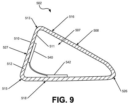
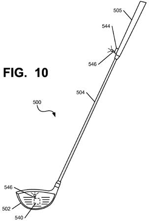
[0082] The device 540 may also be controllable by the user of the ball striking device 500. In the embodiment illustrated in FIGS. 8-10, the ball striking device 500 includes an actuator 544 in communication with the device 540, configured to activate the device 540 to change the temperature of the face 512. As shown in FIG. 10, the actuator 544 is located on the shaft 504 of the ball striking device 500, and may be located within or proximate to the grip 505, in order to provide a convenient and accessible location for the user. The actuator 544 may include a button, a switch, or other such device. In one example, the actuator 544 may include a toggle switch to set the device 540 in a specific mode of operation, such as an ON/OFF switch, a HEAT/COOL switch, a HEAT/COOL/OFF switch, or other such switch. In another example, the actuator may include a button that causes the device 540 to activate when pressed and deactivate when released or pressed again. Further different types of actuators 544 may be used in other embodiments. Additionally, in the embodiment of FIG. 10, the actuator 544 is in wireless communication with the device 540, using wireless antennae 546 on the actuator 544 and the device 540. Such wireless communication can be accomplished by any means, including RF signals, infrared or other optical signals, etc. In another embodiment, the actuator 544 and the device 540 may communicate in another manner, such as by wired connection. In a further embodiment, the actuator 544 may be an integrated part of the device 540 itself In yet another embodiment, the device 540 may be automatically activated, such as by using an accelerometer to determine when a swing of the ball striking device 500 has begun.
[0083] FIGS. 11-12 illustrate a ball striking device 600 in the form of a golf iron, in accordance with at least some examples of this invention. Many common components between the ball striking device 100 of FIGS. 1-3 and the ball striking device 600 of FIGS. 11-12 are referred to using similar reference numerals in the description that follows, using the “600” series of reference numerals. The ball striking device 600 includes a shaft 604 and a golf club head 602 attached to the shaft 604. The golf club head 602 of FIG. 4 may be representative of any iron or hybrid type golf club head in accordance with examples of the present invention.
Pretty cool concept but will it ever make its way into a real Nike Golf product.
Dave Dawsey – The Golf IP Lawyer
PS – Check out more “Would it Work?” posts HERE

