Get Ready to Scratch Your Head and Say “Why Didn’t I Think of That”
Acushnet had an interesting patent issue today for, of all things, a golf shaft. Yes, golfers don’t normally associate the Acushnet name with golf shaft design or manufacturing, but this seems to be the case of a good idea that could not just be swept under the rug, even if it was a little outside of their core strengths. The patent is USPN 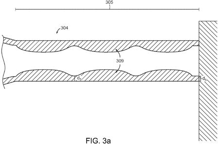
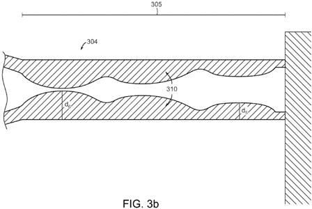
Moving on to FIG. 3a, which shows an enlarged crossed-sectional view of the parallel tip section 305 of a shaft 304 in accordance with one embodiment of the present invention. The internal wall profile may be in a sinusoidal shape across the entire range of the parallel tip section 305 to adjust for the change in the moment created by the shortening of the shaft as well as the change in head weight variation. However, the sinusoidal shape of the internal wall profile 309 could only partially extend across the range of the parallel tip section 305 without departing from the scope of the present invention. Because the ultimate swingweight variation of the golf club needed may not be a truly linear function with respect to the reduction in shaft length and the change in head weight, the internal wall profile 309 of the parallel tip section 305 may fluctuate in a sinusoidal wave shape to correspond with the swingweight variation of a golf club.
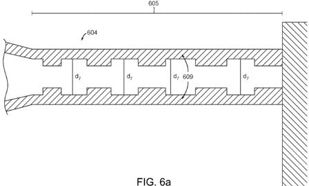
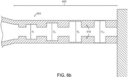
FIG. 6a shows a further alternative embodiment of the present invention wherein the parallel tip section 605 of shaft 600 has a cross-section that shows an internal wall profile 609 that is stair-stepped. Internal wall profile 609, as shown in the current alternative embodiment is in a stair-stepped shape to assist with the removal of additional weight within the internal walls of the shaft in a method that preserves a semi-parallel internal wall profile 609. In this alternative embodiment, the different arrangement and set up of golf club head, length, and shaft may require an even further different internal wall profile 609 in accordance with FIG. 6a to achieve the constant swingweight across the entire set of irons.
Here, in the current alternative embodiment shown in FIG. 6a, the stair stepped internal wall profile 609 may have squared edges, however, stair stepped internal wall profile 609 may have rounded edges, circular edges, or any other edge shape capable of adjusting the weight of shaft 600 to compensate for the swingweight variation all without departing from the scope of the present invention. It should be noted that each of the stair-stepped teeth in FIG. 6a all have the same thickness d.sub.7; however, each of the teeth may have a also different thickness ranging increasing from d.sub.7, d.sub.8, d.sub.9, and d.sub.10 towards the tip of the shaft as shown in FIG. 6b without departing from the scope and content of the present invention. It should be noted that although in this exemplary embodiment shown in FIG. 6b d.sub.10 may be thicker than d.sub.7, the d.sub.7 could be thicker than d.sub.10, causing an increasing internal wall thickness towards the tip of the shaft also without departing from the scope and content of the present invention.
Did it make you scratch your head? If you can’t get enough of the technical details, click the link to read the full PDF of USPN Dave Dawsey – Monitoring Golf Shaft Inventions
