Do You Really Know What “Grain Flow Forged” Means? Honestly?
Golfers see the term “grain flow forged” in Mizuno advertisements all the time, but I suspect only a small portion really understand the concept. Fortunately, a recently published Mizuno patent application educates us on the subject. The application published last week as US Pub. No. 20090247317 titled “Golf Club and Manufacturing Method Thereof,” which explains:
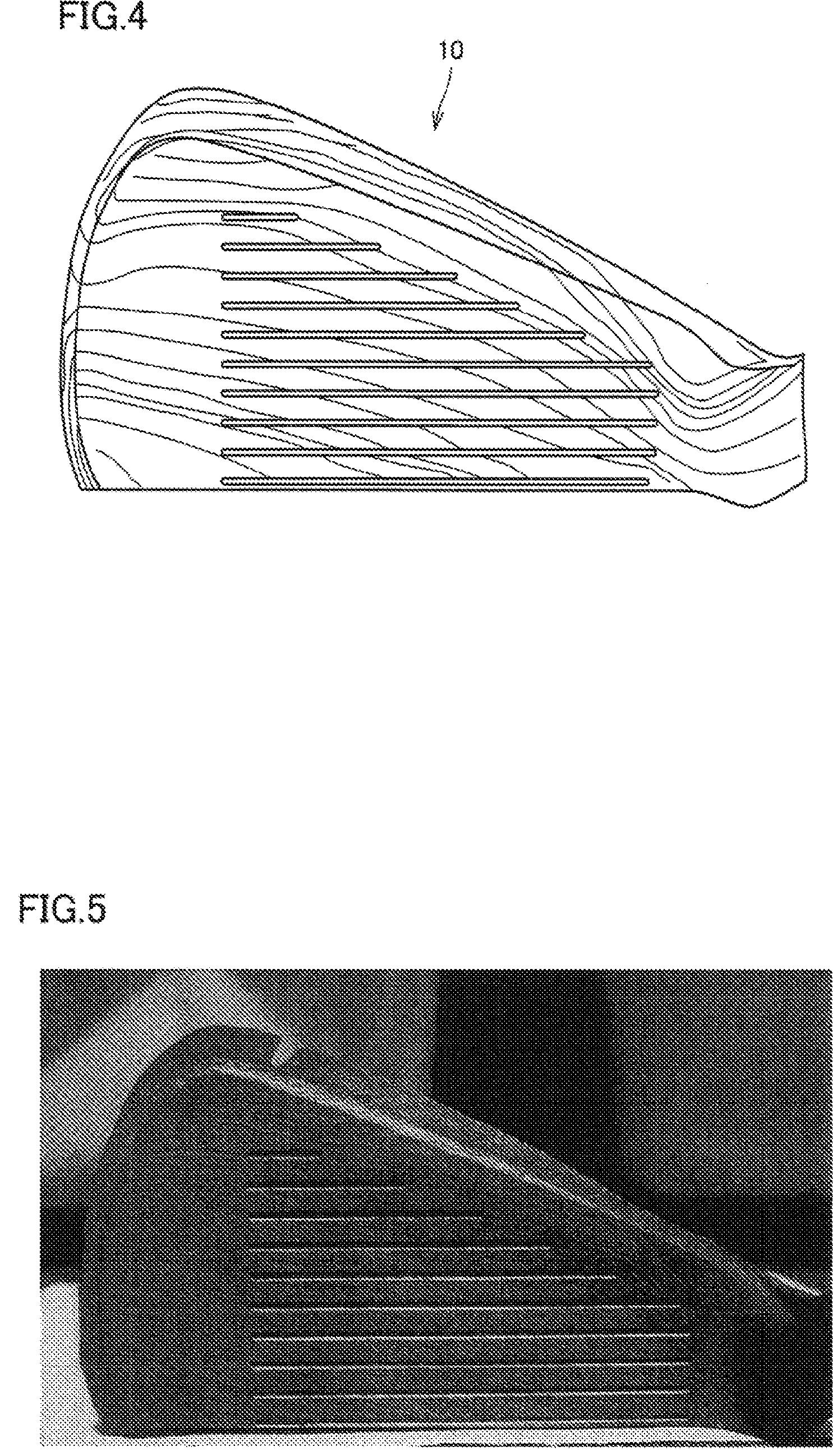
[0011] The present invention provides a golf club, including a head body including a face body with a ball hitting surface and a neck body connecting the face body to a shaft; wherein the head body includes grain flows extending from the neck body to a toe portion of the face body, and the grain flows are formed in the head body and on a surface of the head body.
[0012] The method of manufacturing the golf club in accordance with the present invention includes the steps of: removing outer circumferential portion of a bar-shaped member and thereby reducing diameter of the bar-shaped member; area-reducing one end of the bar-shaped member, of which diameter has been reduced, so that the one end becomes smaller in diameter than the other end; bending the bar-shaped member; and after bending, forging the bar-shaped member to integrally form a face body and a neck body.
[0013] Preferably, the step of removing circumferential surface of the bar-shaped member includes the step of grinding down outer circumferential portion of the bar shaped member and thereby taking out a central portion of the bar-shaped member as the original member before the outer circumferential portion was removed.
[0014] By the golf club in accordance with the present invention, the uncomfortable feeling to the player can be reduced even when the ball is hit by a portion other than the sweet spot.
.
.
.[0058] The method of manufacturing the golf club structured as above will be described with reference to FIGS. 10 to 27. As shown in FIG. 10, a bar-shaped member 21 formed, for example, of carbon steel is prepared. The bar-shaped member has a diameter of, for example, about 50 mm.
[0059] Then, as shown in FIG. 11, outer circumferential portion 22 of bar-shaped member 21 is removed, for example, by cutting work, to reduce the diameter, whereby a central portion 23 of bar-shaped member 21 is obtained. The diameter of central portion 23 is about 27 mm. Generally, bar-shaped member 21 is formed by hot-forging an ingot having larger diameter than bar-shaped member 21, using a mill roll.
[0060] Generally, it is necessary to perform hot forging in a temperature range that ensures satisfactory deformability of each material. It is very difficult, however, to maintain the surface layer of bar-shaped member 21 at a prescribed temperature, and the surface layer temperature tends to be higher than the prescribed temperature.
[0061] Therefore, the temperature of surface layer portion of the ingot tends to be high, resulting in overheat and burning. Overheat leads to coarsening of crystal grains, and burning leads to oxidation and partial melting of impurity at grain boundary. Thus, these two are both factors that hinder formation of grain flows.
[0062] Further, in the process of rolling, the ingot surface is directly pressed by the mill roll, so that grain flows tend to be disrupted. Therefore, grains flows 13 are not much formed on the surface layer of bar-shaped member 21.[0063] On the other hand, temperature of the inside of ingot does not much increase as compared with the surface layer portion and, hence, the inside is less susceptible to overheat and burning. As a result, grain flows generate well. Further, the inside of ingot is not directly pressed by the mill roll and hence, the formed grain flows are not much disrupted.
[0064] Therefore, it follows that larger number of grain flows extend continuously inside the central portion 23 of bar-shaped member 21 than on the outer circumferential portion 22 of bar-shaped member 21.
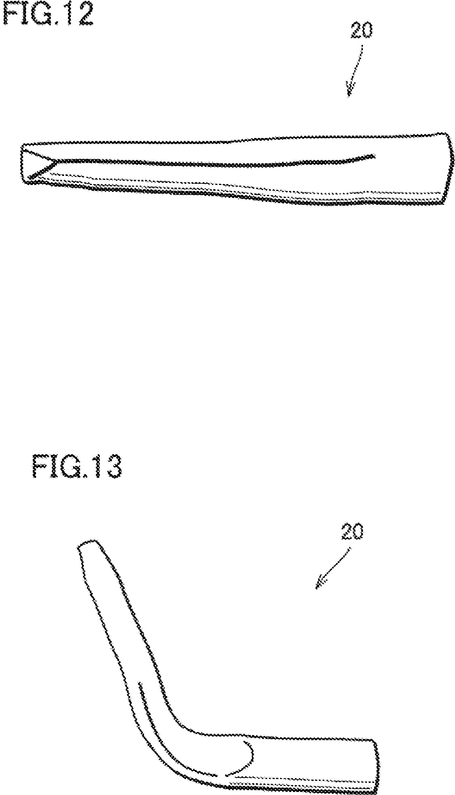
[0065] By removing outer circumferential portion 22 of bar-shaped member 21 shown in FIG. 10 to reduce the diameter and to take out the central portion 23 of bar-shaped member 21, a bar-shaped member 20 having well-formed grain flows such as shown in FIG. 11 can be obtained.
[0066] It is noted here that grain flows 13 are formed inside the bar-shaped member 21 and, therefore, by removing outer circumferential portion 22 of bar-shaped member 21, grain flows 13 come to be exposed on the surface of bar-shaped member 20.
[0067] FIG. 22 is a cross-sectional view schematically showing the cross-section of bar-shaped member 20. As can be seen from FIG. 22, a plurality of grain flows 13 are formed continuously in bar-shaped member 20 and, in addition, grain flows 13 are formed on the surface of bar-shaped member 20.[0068] Further, as shown in FIG. 12, one end of bar-shaped member 20 is subjected to area-reducing process, so that its cross-sectional area is reduced. The area-reducing process is done, for example, by rolling one end of bar-shaped member 20, using a roll. Here, attention must be paid so as not to disrupt grain flows 13 in bar-shaped member 20, as shown in FIG. 23.
[0069] By such plastic working on one side of bar-shaped member 20, cross-sectional area of the said one side is made smaller and hence, density of grain flows 13 on the one side of bar-shaped member 20 can be increased. Thus, as shown in FIG. 23, density of grain flows 13 on one end of bar-shaped member 20 can be increased.
[0070] Neck body 12 is formed on this end, and face body 11 is formed on the other end. Consequently, it is expected that density of grain flows 13 at the neck body 12 can be increased to be higher than the density of grain flows 13 at the face body 11, as shown in FIG. 24.
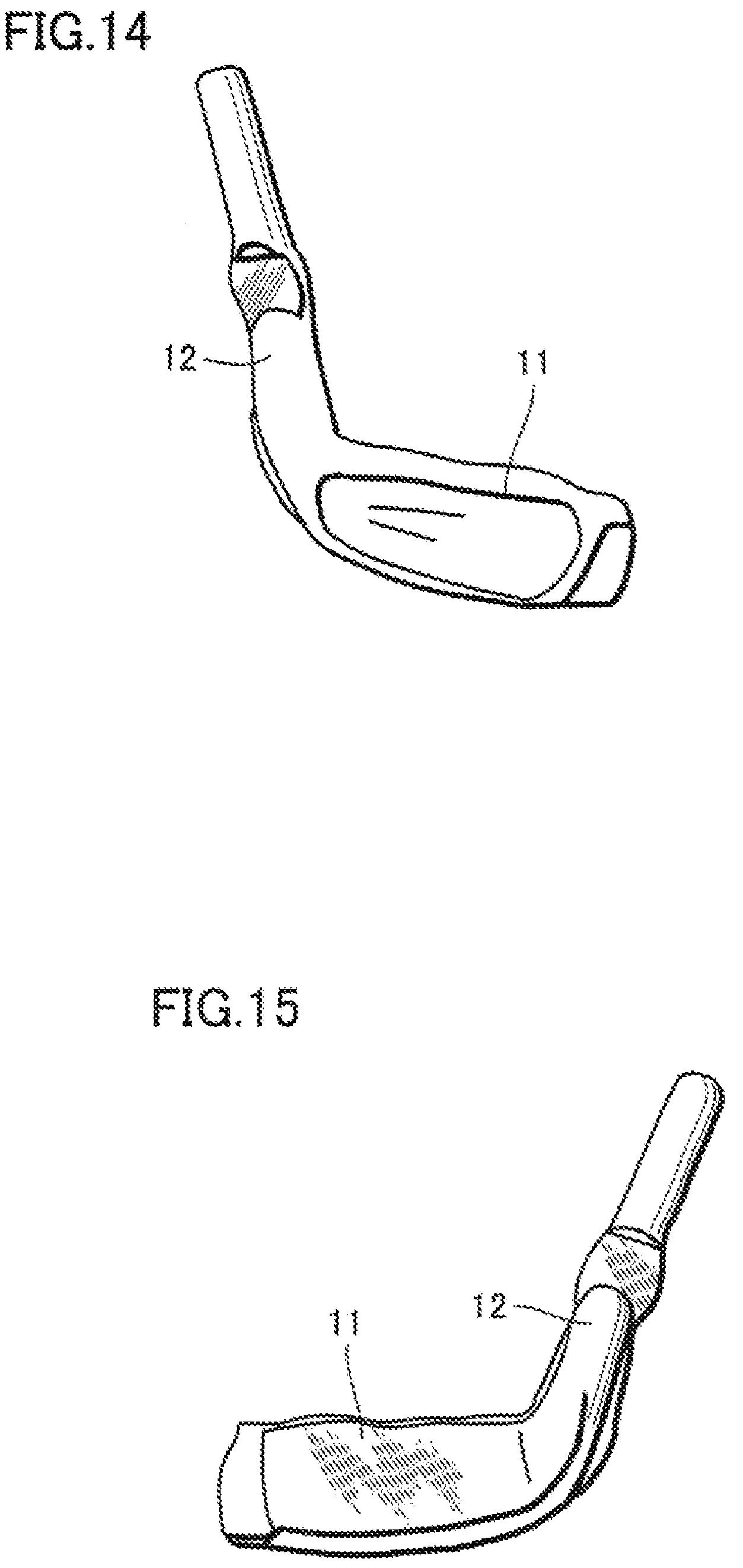
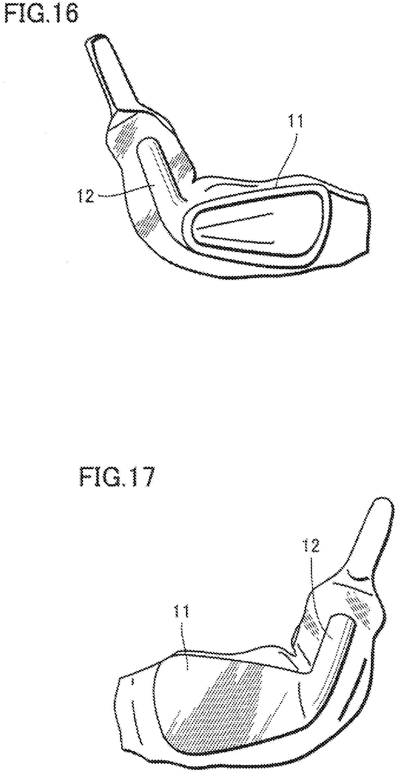
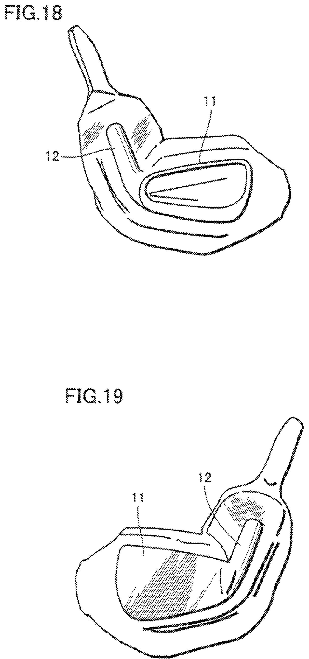
[0071] A process other than the drawing process described above may be adopted, provided that the cross-sectional area of bar-shaped member 20 can be reduced by plastic deformation of one end of bar-shaped member 20.[0072] Next, as shown in FIG. 13 and FIG. 24, bar-shaped member 20 is bent. Thereafter, as shown in FIGS. 14 to 19, three steps of coarse forging are performed, using metal molds and a hammer of 1 ton.
[0073] In the coarse forging process, the bar-shaped member 20 is subjected to stepwise plastic deformation, so that it becomes possible to retain substantially perfect grain flows 13 in the material as shown in FIGS. 25 to 27. Further, in the coarse forging process, the bar-shaped member 20 is subjected to stepwise plastic deformation, so that it becomes possible to have grain flows 13 continuously extend from neck body 12 to face body 11, to have grain flows 13 extend in layers along the hitting surface 15 of face body 11, and to have grain flows 13 distributed uniformly from the side of ball hitting surface 15 to the rear side of face body 11.
[0074] Further, by the three steps of coarse forging, deformation to almost finished shape can be attained as shown in FIGS. 18 and 19. Therefore, the final golf club head can be completed simply by the fine forging process as will be described later. As a result, additional machine processing is unnecessary at the final stage and, hence, partial disruption of grain flows 13 can be prevented.[0075] Next, after trimming, the fine forging process is performed as the finishing process, and details such as score lines are formed, as shown in FIGS. 20 and 21. Through the above-described steps, head body 10 having integrally formed face body 11 and neck body 12 can be obtained, with substantially perfect grain flows 13 maintained. Head body 10 as such is subjected to plating, so that plated layer 70 is formed on the surface of head body 10, and shaft 30 and the like
are mounted, whereby a golf club is complete.
Interesting stuff. The Mizuno website actually contains an interesting video titled “The Art of Forging.” Check it out.
Dave Dawsey – Monitoring Golf Technology Inventions
PS – check out other golf iron invention posts HERE
