Club Manufacturers Are Starting to Design for the Fact That Most Golfers Don’t Hit the Ball in the Center of the Club Face
It is hard to believe that it has been over two years since I posted Club Face Adjustability, Is It The Next Big Thing about an Acushnet patent directed to variable driver face stiffness. That post was even a follow-up to one a year earlier titled The Next Step in Club Head Adjustability regarding a prior Acushnet patent directed to coefficient of restitution (COR) adjustability, or the ability to adjust the stiffness of club’s face.
Well, apparently it is a concept that is also of interest to Nike Golf, as this week they had a patent application publish titled “Golf Club Head or Other Ball Striking Device Having a Reinforced or Localized Stiffened Face Portion,” which describes the invention as:
A ball striking device, such as a golf club head, has a head that includes a face configured for striking a ball and a body connected to the face. A brace extends from an inner surface of the body or from a perimeter weight system to a contact point on the rear surface of the face. This brace may extend from the sole or a sole oriented perimeter weight member to the rear surface of the face. The brace applies force to the face (at least when the face is flexed by a threshold amount) such that the area of the face surrounding the contact point has less flexibility relative to other areas of the face located away from the contact point. The brace and club head may include structures that allow one to control and customize the force applied to the face.
The application goes on to explain:
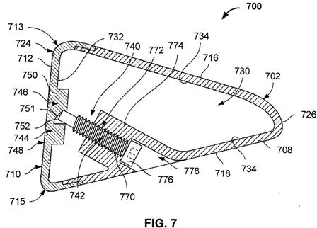
[0070] FIG. 7 illustrates another example ball striking device 700 in accordance with this invention, one that is structurally similar to the ball striking device 100 of FIGS. 1 through 3 and contains many of the same or similar components. The common components of the ball-striking device 700, such as the head 702, body 708, and face 712, are referred to similarly in this drawing as referred to above with respect to the ball striking device 100 of FIGS. 1-3, although using the “700” series of reference numerals. The head 702 of the ball striking device 700 of FIG. 7 contains an adjustable brace 740 that is structured differently from the fixed brace 140 described above with respect to FIG. 2.[0071] The adjustable brace 740 includes an adjustable member 742 operable to allow adjustment of the force applied to the face 712 by the brace 740. In the example structure 700 shown in FIG. 7, the adjustable member 742 includes a screw 770 that is received within a threaded passage 772 and exerts a force on the inner surface 732 of the face 712, such that turning the screw 770 is operable to adjust the force applied to the face 712. The adjustable member 742 extends from an inner surface 734 of the body 708 to the inner surface 732 of the face 712 to exert force on the face 712. In this example structure 700, a threaded tube 774 extending at least partially from the sole 718 toward the face 712 defines the threaded passage 772 there through. Generally, the adjustable member 742 is accessible through the outer surface of the head 702. More specifically, in the structure 700 illustrated in FIG. 7, the screw 770 has an engagement portion 776, such as a screw head, that is accessible at the sole 718 of the head 702. The engagement portion 776 may be adapted to be engaged by one or more of various tools and devices, such as a hex-head wrench, a torque wrench, an Allen wrench, a Phillips head screwdriver, a standard (flat) screwdriver, or other known tool or device. The sole 718 has a recess 778 proximate the screw head 776 so that the screw head 776 is recessed into the body 708 and does not protrude out of the body 708, potentially affecting a user’s swing by catching on the ground or an external object during swinging. Optionally, if desired, the recess 778 may be closed off, e.g., using a cover member or plug that engages the sole or the adjustable member.
[0072] The force applied to the face 712 by the brace 740 can be adjusted by tightening or loosening the screw 770. As such, turning the screw 770 to extend the screw 770 further into the head 702 will exert more force on the face 712, and turning the screw to retract from the face 712 will reduce the force exerted on the face 712. Generally, the stiffness and size of the stiffened area 748 on the face 712 increases with increased force applied to the face 712. A scale or other orientation marker may be included on the head 702 and/or the adjustable member 742, so that a user can reliably return the adjustable member 742 to a default or previous orientation. Additionally, such an orientation marker or scale may include multiple indicia, such as approximate COR values for the face 712 or approximate force applied by the brace 740, based on the position of the adjustable member 742 (and thus the force applied by the brace 740 to the face 112).
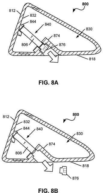
[0075] FIGS. 8A through 8D illustrate additional example features that may be incorporated into golf club heads in accordance with at least some examples of this invention. The club head 800 shown in this example structure may be similar to that shown in FIG. 7, including a tube 874 allowing access to the interior 830 of the club head 800. In this example structure 800, however, the overall brace 840 includes multiple parts. More specifically, the brace includes a contact portion 844 (engaged with or integrally formed on a rear surface 832 of the face 812), a removable brace portion 806, and a cap member 876 (which, optionally, may apply a force to press and hold brace portion 806 between the tube 874 and the contact portion 844). As shown in FIG. 8A, at least some of the brace portion 806 may remain within the tube 874. The cap member 876 may engage and secure to the tube 874 in any desired manner, such as via a threaded connection, via a cam connection, via another mechanical connection, etc. The brace 840 may support and/or supply force against the rear surface 832 of the face 812, e.g., in the various manners described above.
[0076] In some instances, it may be desired to provide a club head 800 with a more flexible face (e.g., to improve the “trampoline effect” for players with slower swing speeds, etc.). On the other hand, in some instances, a less flexible face may be desired (e.g., to prevent failure of faces for players with very high swing speeds, etc.). The club head structure 800 of FIGS. 8A through 8D allows for some COR adjustment and/or customizability.
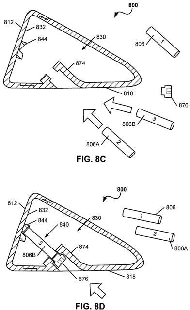
[0077] For example, as illustrated in FIG. 8A, the club head 800 is initially configured with brace portion 806 extending between the contact portion 844 and the cap member 876. Should a user or club fitter determine that this specific brace portion 806 is not providing the desired performance, it can be interchanged with a different brace portion having different characteristics. As an initial step in this interchange, as shown in FIGS. 8A and 8B, the cap member 876 is removed from the tube 874 (e.g., by unscrewing it, by otherwise disengaging it, etc.). This allows the user access to the interior chamber 830 of the club head 800 and to the brace portion 806.
[0078] Optionally, if desired, the brace portion 806 may be connected to the cap member 876 such that the brace portion 806 may be removed from the club head 800 at the same time that the cap member 876 is pulled from the tube 874. As another alternative, if desired, the brace portion 806 may be fit into a receptacle provided in the contact portion 844 such that the ends of the brace portion 806 contact and extend between the receptacle provided in the contact portion 844 and the end of the tube 874. The tube 874 may extend any desired portion of the distance between the sole 818 and the contact portion 844, including this entire distance. As yet additional options, if desired, the brace portion 806 may be loosely fit within the area between the tube 874 and the contact portion 844, or it also may be engaged with at least one of these members, e.g., by a threaded connection, by a turnbuckle assembly, by another mechanical connector system, etc. Then, as shown in FIGS. 8B and 8C, the brace portion 806 may be removed from the interior 830 of the club head 800 (optionally, some sort of tool may be required to make this extraction, such as engagement of a pulling mechanism with the exposed end of the brace portion 806).
[0079] Once the original brace portion 806 is extracted, a different brace portion (e.g., brace portions 806A or 806B can replace it, and the cap member 876 may be replaced. See FIGS. 8C and 8D. The various brace portions 806, 806A, and 806B may have different stiffnesses or flex characteristics, different lengths, different materials, different hardnesses, different longitudinal flexibility, etc., and they may include indicia thereon that indicate the relevant characteristics. A club fitter or a club user can test various different brace portions 806, 806A, and 806B and select the one best suited for their use (e.g., one that provides the best results, one that feels most comfortable to the player, one best suited to existing play conditions (for example, to provide a high or low launch, to provide the desired spin characteristics, etc.), one that prevents excessive face deformation due to the swing speed, etc.).
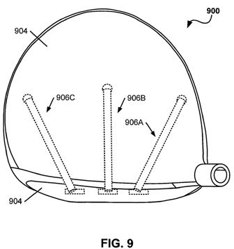
[0080] FIG. 9 illustrates additional potential features of golf club heads 900 in accordance with at least some examples of this invention. This figure illustrates that the brace system may be located at multiple different locations and/or different orientations with respect to a club head face 902 and a club head body 904. For example, as shown in FIG. 9, a first brace system 906A may be located in the heel area of the club head structure 900 (to apply force at the heel area of the face 902), a second brace system 906B may be located in the central area of the club head structure 900 (to apply force at the central area of the face 902), and a third brace system 906C may be located in the toe area of the club head structure 900 (to apply force at the toe area of the face 902). If desired, braces inserted through any of the inlet ports may be sized, shaped, and adapted to extend to any of the desired face contact locations (e.g., so that a brace inserted at the toe end contacts the middle or heel location on the face).
Oh, it can also be applied to irons….
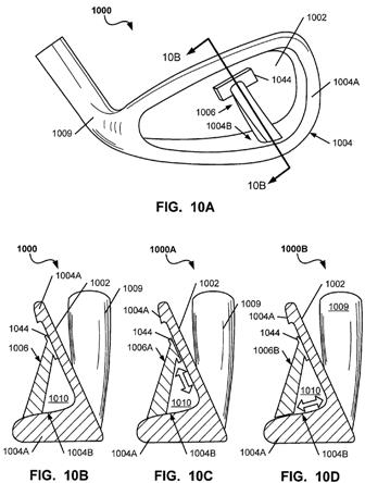
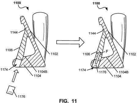
[0083] While the invention has been described above in conjunction with wood-type golf clubs and golf club heads (including drivers), aspects of this invention are not limited to such clubs. Rather, the various aspects and features of this invention may be applied for use in iron-type golf clubs and golf club heads. FIG. 10A illustrates an example of an iron-type golf club head 1000 in accordance with some aspects of this invention. As shown, the iron-type golf club head 1000 has a ball striking face 1002 (the rear surface of which is shown in FIG. 10A), a body portion 1004 (including one or more individual parts) including a perimeter weighting system 1004A, and a hosel member 1009 for connecting to a shaft (not shown in FIG. 10A). The perimeter weighting system 1004A and the rear surface of the ball striking face 1002 define a rear cavity back iron structure. A brace system 1006 extends from the rear surface of the ball striking face 1002 to an interior surface 1004B of the sole portion of the perimeter weighting system 1004A. As further shown in FIG. 10A, the brace system 1006 may include an elongated contact area 1044 located at a desired portion of the club head face 1002 to provide face support and/or localized stiffening, as described above. The ends of the brace system 1006 may contact the face 1002 and/or the perimeter weighting system 1004A at any desired locations, and the brace 1006 may extend at any desired angle without departing from this invention. In some example structures according to the invention, the brace 1006 will intersect the perimeter weighting member 1004A as far rearward as possible, e.g., within the rear 50%, or even the rear 25% of the club head structure.
Who knows, maybe one of these will actually make it to the market in the next few years!
Dave Dawsey – Keeping an Eye on Driver Inventions
PS – check out some interesting golf tee inventions here
