Chalk One Up for the USGA
Remember all the press coverage the USGA got when they developed a simple procedure to test whether grooves conform to the new rules? OK, it wasn’t a lot of press but I do remember some. Well, someone at the USGA was smart enough to say “hey, maybe we should patent this!” They did. Last week the USGA was granted USPN The test procedure for determining groove conformance employs a replicating compound to obtain a self-supporting mass with a negative image of the grooves of a club face. A thin test specimen strip is sliced from the mass and then scanned to form an electronic trace of the profile of the ribs. A negative image of the profile of the ribs is then obtained as a replica of the profile of the grooves and the grooves measured to determine conformance to USGA Rules. A protective covering may be placed on the self-supporting mass to insure the integrity of the ribs during slicing.


The patent goes on to explain:
In accordance with The Rules of Golf, 2008-2009, there are certain standards that have been promulgated by the United States Golf Association for golf clubs. In particular, Appendix II that relates to the design of clubs provides under Section 5 certain specifications for a club face, including smoothness, lack of any degree of concavity, roughness, grooves and punch marks, decorative markings and markings on non-metallic club faces and putter faces. In particular, Section 5C (impact area markings) provides certain standards for a club having grooves in the impact area of the club face.
From time to time, a need arises to determine if a club face conforms to The Rules of Golf. The following provides a test procedure for determining the conformance of a golf club face.
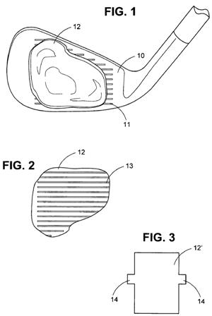
As a first step in the test procedure, the club face 10 of a golf club, such as an iron, is cleaned particularly to remove any paint that may have been applied to the grooves 11 in the face 10. Cleaning may be carried out using any suitable fluid, water, an alcohol swipe, solvent, compressed gas or a mechanical action.
Referring to FIG. 1, after the club face 10 has been cleaned, a curable casting or replicating compound is applied to the grooved face 10. For example, the compound may be a two part rubber compound that may be mixed in the hands and applied to the area of interest on the club face 10, usually the center of the club face 10. Typically, the hands are used to squeeze the compound into the grooves 11 in the club face 10.
.
.
.
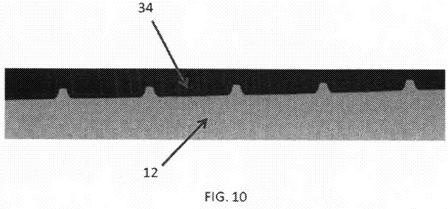
After curing, the compound is peeled from the golf club as self-supporting casting 12. As indicated in FIG. 2, this casting 12 has a plurality of ribs 13 on the underside that are a replica of the grooves 11 of the golf club face 10.
.
.
.
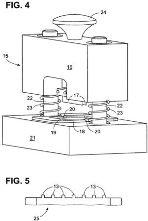
Referring to FIG. 4, a slicing apparatus 15 is provided for obtaining a test specimen from the cured compound (self-supporting casting) 12. This slicing apparatus 15 has a guillotine assembly 16 that includes a pair of cutting knives 17 that are disposed in parallel spaced apart relation for cutting a thin strip as a test specimen from the cured compound. The knives 17 must be of extreme sharpness to achieve good cutting.
.
.
.
The test specimen strip 25 has a profile corresponding to a cross-section of the casting 12 and allows the strip 25 to be evaluated to determine conformance with a predetermined standard as described below.
.
.
.
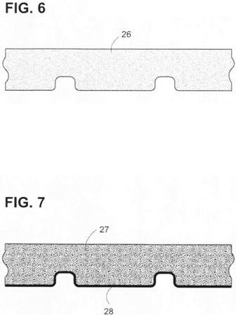
Thereafter, the test strip 25 is scanned, for example, on a flat bed scanner (not shown) to form an electronic image of the profile of the ribs 13 on the strip 25 in any suitable electronic format, and preferably a lossless format, such as a gray scale bitmap 26. (See FIG. 6)The scanned image is then transmitted to a computer at a central location, preferably a test lab, or to an onsite computer. As received, the scanned image is converted from gray scale bitmap 26 (see FIG. 6) to black and white image 27 (see FIG. 7) by setting all the pixels with an intensity level less than or equal to a threshold level to 0 (black) and pixels with intensity levels greater than the threshold to 1 (white). The threshold may be in the range of 0 to 1, preferably 0.25 to 0.75 and most preferably 0.55. The result is a negative image of the profile of the ribs of the specimen and is a replica of the profile of the grooves 11 of the grooved club face 10 (see FIG. 7). The profile of the grooved replica is the boundary 28 of the black and while regions of the image.
In addition to arbitrarily setting the threshold, it is possible (and may be even preferable) to employ an automated threshold algorithm to determine the optimum pixel intensity to convert a gray scale image to black and white. For example, Otsu’s method may be employed which chooses the threshold to minimize the intraclass variance of the thresholded black and white pixels.
Alternatively, a color image of the test strip 25 may be captured. In this case, individual red, green and blue intensity values may be used independently or combined via a linear transformation to convert to a black and white image. That is, the red, green or blue image intensities may be used and scaled from 0 to 1. Alternatively, the red, green and blue intensities may be combined via a linear transformation to give a single intensity level at each pixel. An example might be to average all three intensities and scale from 0 to 1. Another example would be to combine the three colors by taking 30% of the red value, 59% of the green value and 11% of the blue value and scaling from 0 to 1. The intensity image is then converted to a binary, black and white image by converting all intensities less than or equal to a threshold to 0 (black) and all intensities greater than the same threshold to 1 (white). The profile of the face geometry is then defined as the boundary between the black and white regions.
The profile of the negative image is then measured by suitable software within the computer to determine conformance of the grooves with the standards provided by the USGA, Determination of Groove Conformance, Revision 1-09, January, 2009.
The measurements and analyses are taken to determine, for example, groove width, groove depth, groove separation, groove consistence, area (A) over width (W) plus separation (S), i.e. A/(W+S), and edge radius.
The test procedure may be carried out completely in a test lab, particularly where several golf clubs are to be tested for groove conformance. Likewise, the entire test procedure may be carried out at a golf course site provided the equipment for performing the test is available, such as, the slicing apparatus, a scanner and a computer having the software required for performing an analysis.
The test procedure is relatively simple and may be performed within a minimum of time should a need arise for testing a golf club during a golf tournament.
.
.
.
See, contrary to most media reporting, there are some smart folks at the USGA!
Dave Dawsey – The Attorney with an Eye on the USGA
