
Yet Another Level of Adjustability in Golf Club Design
There is no doubt that adjustability is great for marketing hype, but I really don’t know anyone that uses it beyond the first few rounds played with their new adjustable toy. Taylor Made has led the adjustability movement with their movable weight technology (MWT) and flight control technology (FCT), and now they have another adjustability feature on the drawing board. The new technology is disclosed in a patent application that recently published as US Publication No. 20090253530 titled “Golf Club Grip.” The application includes the following drawings and description:
[0002] Golf club grips commonly include a reminder rib to help a player properly orient his or her hands on the club. A rib can be either placed against the palm or fingers (e.g., index finger, thumb, or some other finger). By using a reminder rib a person can train himself to have a neutral address position, meaning that a golf club is held at a neutral angle relative to a golf ball. With this orientation, the ball is more likely to fly straight as opposed to curving in one direction or the other when the club face is “open” or “closed.” Alternatively, a reminder rib can serve as a reference for golfers who deliberately choose to open or close the club face to compensate for his/her swing, golf course layout, weather, or other factors. For example, a club with a deliberately closed face could assist players in hitting the ball to the left side of the fairway from the player’s point of view, or reducing slicing. Additionally, an open face would tend to help a player to hit high cut shots, eliminate hook shots caused by an outside-in swing (e.g., the player bringing the club closer to the player’s body through the course of the swing), or keeping the ball on the right side of the fairway instead of the left side of the fairway from the player’s point of view. By adjusting whether the club face is open or closed, the player can change the ball flight trajectory or compensate for a tendency to hit to the left side or right side of the fairway or green.
[0003] Additionally, a closed face on a golf club would tend to generate a lower flight trajectory which could be desirable if there was a strong wind. This lower trajectory also causes the golf ball to roll more once it lands on the fairway or green. By contrast, an open faced golf club generally causes the ball to fly higher. This higher trajectory can cause the ball to roll less once it lands, thus enabling a player to “place” the golf ball on the fairway or green.
.
.
.
.
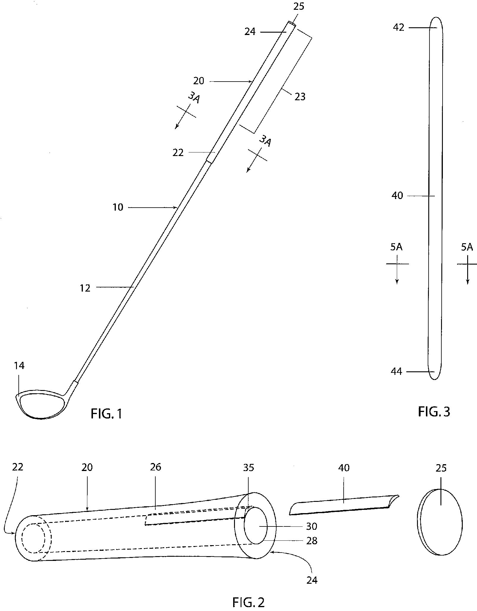
[0007] In one embodiment, the present disclosure describes a golf club grip comprising a generally elongated cylindrical member including an exterior surface and an interior surface that defines a shaft receiving space extending end to end through the cylindrical member. The receiving space forms an upper end opening and a lower end opening. The cylindrical member further includes a grip section defined by a portion of the exterior surface and the interior surface. The grip section includes a slot extending at least a portion of the length of the grip section and having a longitudinal axis that is generally parallel to the axis of the cylindrical member. A shim is generally disposed inside the slot, and extends at least partially through the grip section where the club is gripped. The shim preferably has a generally arc-shaped cross-section with an inner surface and an outer surface. The shim and slot are configured such that the shim is removable from the slot. Preferably, the slot and shim are sized and shaped and formed of materials that allow the shim to be snugly inserted into and removed from the slot and yet remain securely in place, with minimal shifting or angular movement, when the club and grip are subject to forces generated by a golf swing.[0008] Another embodiment of the present disclosure describes a golf club comprising a shaft, a club head affixed to one end of the shaft, and a grip located around at least a portion of another end of the shaft. The grip section includes a slot extending at least a portion of the length of the grip section and having an axis that is generally parallel to the axis of the shaft. The grip section also includes a shim generally disposed inside the slot. The shim is about the length of the grip section and has a generally arc-shaped cross-section with an inner surface and an outer surface. The shim and slot are configured such that the shim is removable from the slot.
[0009] Yet another embodiment of the present disclosure describes a golf club grip comprising a generally elongated cylindrical member including an exterior surface and an interior surface. The cylindrical member defines a shaft receiving space extending end to end through the cylindrical member and forming an upper end opening and a lower end opening. The cylindrical member further includes a grip section defined by a portion of the exterior surface and the interior surface. The grip section includes a slot having a bore disposed between the exterior surface and the interior surface, which extends at least a portion of the length of the grip section and has a longitudinal axis that is generally parallel to the axis of the cylindrical member. A shim is disposed generally inside the bore and preferably extends at least the length of the grip section. The shim preferably has a generally arc-shaped cross-section with an inner surface and an outer surface, and further includes an elongated ridge disposed along the length of the outer surface. The elongated ridge is generally parallel to the longitudinal axis of the bore. In one embodiment, the arc-shaped cross section of the shim covers an arc of roughly 10 degrees. Furthermore, the elongated ridge causes no more than 1 mm variance between a narrowest portion of the grip section and a thickest portion of the grip section when the shim is inserted into the grip section. Finally, the bore and shim are configured such that the shim is removable from the bore.
.
.
.
[0026] FIG. 5A illustrates a cross-section of a preferred embodiment of the shim 40 taken along line 5A-5A of FIG. 2, the shim preferably having a generally arcuate shape with a radius of curvature corresponding generally to the radius of the bore of the grip. It can be seen that the shim 40 includes a raised portion 50 along one outwardly facing side. The raised portion or bulge preferably extends the full length of the shim. In one embodiment the angle between a midpoint 52 of the shim 40 and apex 54 of the raised portion 50 is between 0 and about 15 degrees, preferably about 5 degrees to 15 degrees, and most preferably about 5 degrees to 10 degrees. The shims may be offered to golfers individually or with one or more shims grouped together as a kit. Other options might include offering one or more shims with the grip or with a given club (e.g., a driver or a specific iron or wood) as a set. An exemplary kit might include two shims having an angle between a midpoint of the shim and the apex of 5 degrees and 10 degrees, another kit might include three shims of 5 degrees, 8 degrees and 12 degrees and so on, although other kits may include shims varying by smaller degree increments such as 1 degree increments.[0027] A difference of 5 degrees in how a user holds a club can make a noticeable difference in the flight path of the golf ball. However, a player may prefer a grip reminder orientation that falls between two preset orientations offered by prior art grips (see Cacicedo grip as described above), requiring the player to choose the best of the limited options available. By providing a plurality of different shims that vary by increments as small as 1 degree, a player’s options are increased and the player can choose which option is preferable for the given course, we
ather, or conditions related to a specific player.
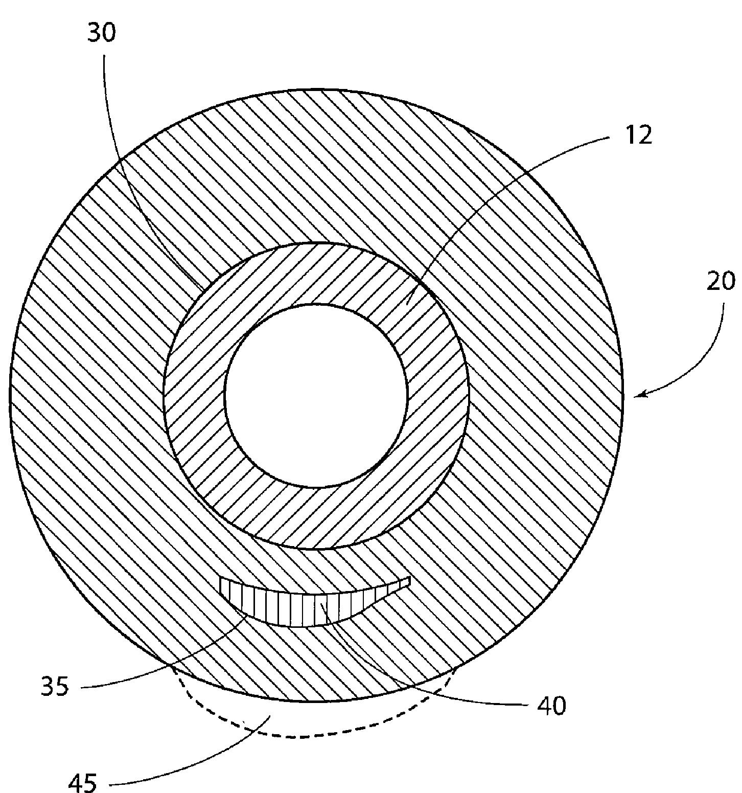
[0028] The club grip 20 preferably is adhesively bonded to the shaft 12 which is received within the shaft receiving space 30 of the club grip. Once the grip is in place, the shim 40 is inserted into the bore 35 of the club grip 20, and the grip cap 25 is affixed to the end of the club grip 20. As mentioned above, the grip cap 25 may prevent the shim 40 from sliding out of the club grip 20 during use.[0029] With the shim 40 in place, the grip has a longitudinally extending bulge on one side due to an increased radial thickness caused by the shim. Preferably, the radial difference is 1 millimeter or less between the thinnest and thickest walls of the grip, so as to stay in conformance with United States Golf Association (USGA) rules. Generally the narrowest radial section is measured as the shortest distance from the axis of the golf club 10 to the outer surface 26 of the club grip 20, and the thickest radial section is measured as the greatest distance from the axis of the golf club to the outer surface of the club grip. The bulge serves as a reference point or reminder to allow the golfer to align his/her grip in a desired orientation relative to the club head/face. The location/orientation of the “reminder” may vary from golfer to golfer, depending on many factors including preference for an open, closed or neutral club face, desired flight path of the ball, type of course, desire to counter flawed swing mechanics, desired location of reminder relative to golfer’s hands, etc. For example, the club grip 20 may be adhered to the shaft 12 such that a user holding the club grip 20 in a normal fashion will align the crease of his or her top hand with the shim 40. In another example, the club grip 20 is adhered to the shaft 12 such that the user aligns his or her top thumb with the shim 40. In yet another example, the shim 40 may be aligned with the palm of the user’s top hand.
[0030] It will be understood that a club grip 20 having a shim 40 with a 5 degree angle as described above may cause a user holding the grip 20 to rotate the club face 14 by 5 degrees when the user swings the golf club 10, thus slightly “opening” or “closing” the club face 14, depending on whether the shim reminder is positioned 5 degrees clockwise or counterclockwise relative to a “neutral” grip position. This could be desirable to correct an error in the user’s swing or to compensate for wind conditions, ball placement, course layout, or other conditions. It will be noted that though this correction factor is relatively small, and for inexperienced golfers would feel similar to a club grip 20 with a shim 40 with no correction angle, it would still have a noticeable effect on the flight of the golf ball in many instances. It will be further appreciated that because the shim 40 extends parallel to the longitudinal axis of the shaft, a shim 40 with a 5 degree angle could either “open” or “close” the club face 14 with respect to a golf ball depending on whether the top part 42 or the bottom part 44 of the shim 40 is inserted into the bore 35 first. This feature is due to the 5 degree asymmetrical offset bulge integrated into the design of the shim. When one end of the shim is inserted into the grip, an elongated reminder reference is provided with a 5 degree offset (for example) on one side of the shim’s neutral center line, and when the opposite end is inserted the reminder reference is provided with a 5 degree angular offset on the other side of the insert’s neutral center line.
Interesting. So, what do you think the new acronym will be? Perhaps, adjustable reminder rib (ARR).
Dave Dawsey – Keeping an Eye on Golf Grip Inventions
PS – check out other golf grip patent related posts here