
Yellow and Blue Make a Green Golf Ball, but Only if You Achieve a High Spin Rate
I am about to show you the coolest golf invention that will do absolutely nothing to improve my game. Incredibly creative nonetheless and definitely in my favorite top 10 since starting this blog. The invention is a spin indicating golf ball by Nike.
The invention was disclosed in a patent application that published this week as US Pub. No. 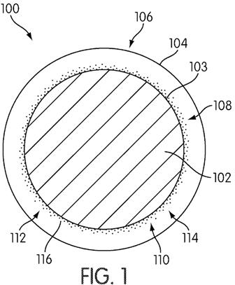
[0024] FIG. 1 is a cross section of an embodiment of golf ball 100. Golf ball 100 has a series of radially or circumferentially arranged layers. The innermost layer is core 102. Core 102 can be any of a variety of cores commonly used in golf balls. For example, core 102 could be liquid filled or solid filled. The solid may be rubber, resin, or any other suitable material. The core may also include various types of weights. Core 102 may also include a wound cover. A person having ordinary skill in the art can select a core that produces the technical and flight characteristics that are desirable. An optional mantle layer is not specifically shown in the FIGS., but may surround and may be positioned outward of core 102. Inner layer 103 is shown in FIG. 1 as being the outer surface of core 102, but may instead be defined by an outer surface of the optional mantle layer or another layer outward of core 102.
[0025] Top or outer layer 104 is radially or circumferentially outward of the inner layer 103 and is shown in simplified form. In a commercial version, the outer layer, and in particular, outer surface 106 of outer layer 104, is configured to be struck by a golf club. Accordingly, outer layer 104 may include various dimples, frets or lands, projections, printing, or any other features that a designer thinks would be desirable in affecting the flight path of the ball 100. Outer layer 104 may be designed to be scuff resistant. In the embodiment of FIG. 1, outer layer 104 is translucent. Inner layer 103 and outer layer 104 are spaced from one another and a space or cavity 108 is between the inner layer 103 and outer layer 104.
[0026] Between inner layer 103 and outer layer 104 is a first fluid 110. First fluid 110 may have a variety of properties. However, it is desirable that the molecules or particles that comprise first fluid 110 be able to move in the cavity 108. First fluid 110 may be made of a variety of types of materials or of a single material. Some materials comprising first fluid 110 may have greater density or viscosity than others. First fluid 110 may include pigments having two colors. The two colors can be any two colors that are distinguishable from one another. First pigment 112 is a first color and second pigment 114 is a second color different from the first color.
[0027] It may be desirable for outer layer 104 of any of the disclosed embodiments to be translucent or transparent. A transparent ball is also translucent. The use of a first fluid having multiple colors is most useful if the color difference can be seen or determined through the outer layer.
.
.
.
[0030] Turning again to the embodiment shown in FIG. 1, inner layer 103 and first pigment 112 are selected to mutually attract one another. For example, one of the inner layer and the pigment could include a magnetic element and the other could include a magnetically active metal that is attracted to the magnetic element. Alternatively, inner layer 103 and first pigment 112 could have various types of ionic or other attraction that cause the first pigment to settle into a consolidated position along the surface of inner layer 103 when ball 100 is at rest. In such an instance, it may be desirable for inner layer 103 to be a separate layer from the core. As shown in FIG. 1, the first pigment 112 may be a plurality of pigment particles 116.
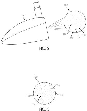
[0031] FIG. 2 is a schematic showing ball 100 just after impact by club 120. As shown in FIG. 2, the impact of club 120 against ball 100 imparts a spin to ball 100. Regardless of which club is selected or how the ball is struck, it is highly likely that some sort of spin will be imparted to the ball. In many cases, the spin imparted to the ball will create a force on each pigment particle 116 in first pigment 112. This force may be a centrifugal force, in whole or in part. The force may be sufficient to overcome the attractive force between first pigment 112 and inner layer 103. This may cause one or more of pigment particles 116 to leave the consolidated position shown in FIG. 1 and move to a dispersed position, as is shown by an exemplary pigment particle 118 visible through outer layer 104 among the particles of second pigment 114.
[0032] FIG. 3 shows ball 100 after the first pigment 112 and first pigment particles 116 have reached a dispersed position. The density of first pigment particles 116 relative to particles of second pigment 114 measures the amount of spin imparted to ball 100 by the stroke of club 120. This measurement indicates to a golfer how much spin is applied or imparted to ball 100 by his or her stroke. Once ball 100 finishes its flight and roll after the stroke, first pigment 112 returns to the consolidated position shown in FIG. 1 after an effective length of time. The effective length of time will vary depending on factors such as the relative density of the first pigment and the second pigment, the amount of spin imparted to the ball, and the air temperature. These factors are not exclusive, but will depend on other factors as well.
[0033] It may be desirable in this or other embodiments for the pigments used to be of different and possibly contrasting colors. It may also be desirable for the pigments used to be UV reactive. In such an instance, the pigments would be arranged in the same manner as disclosed. However, when exposed to light from the sun or another UV source, the pigments would change from one color to another. In some instances, it may be desirable to select pigments that all appear white when not exposed to UV light in order to preserve an overall white appearance of the ball. In such an instance, when the ball is exposed to UV light during the course of play, the pigments would change color in flight and then could be capable of returning to a white color at rest. In such an instance, where the present disclosure refers to pigments having differing colors, these colors would be the colors that the pigments would have upon UV exposure, rather than their colors without such exposure.
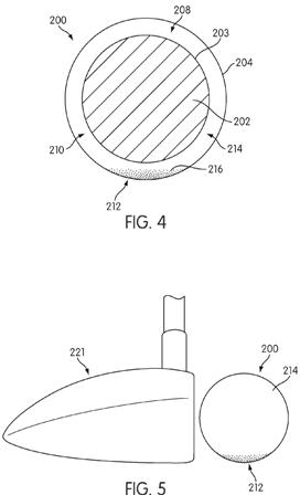
[0034] An alternative embodiment is shown in FIGS. 4-7. FIG. 4 is a cross section of an embodiment of golf ball 200. Golf ball 200 has a series of radially or circumferentially arranged layers. The innermost layer is core 202. Core or 202 has the same properties as described above in connection with core 102 and inner layer 203 has the same properties as
described above in connection with inner layer 103. Top or outer layer 204 is radially or circumferentially outward of inner layer 203 and has the same properties as described above in connection with outer layer 104. Inner layer 203 and outer layer 204 are spaced from one another and a space or cavity 208 is between the inner layer 203 and outer layer 204.
[0035] Between inner layer 203 and outer layer 204 is a first fluid 210. First fluid 210 may have a variety of properties. However, it is desirable that the molecules or particles that comprise first fluid 210 be able to move in the cavity 208. First fluid 210 may be made of a variety of types of materials or of a single material. Some materials comprising first fluid 210 may have greater density or viscosity than others. First fluid 210 may include pigments having two colors. The two colors can be any two colors that are distinguishable from one another. First pigment 212 is a first color and second pigment 214 is a second color different from the first color.
[0036] In FIG. 4, ball 200 is in a rest position and first pigment 212 has settled to the bottom of cavity 208 in its consolidated position. Among the reasons pigment particles 216 of first pigment 212 may settle to the bottom of the cavity 208 is if first pigment particles 216 on average are of a higher density or weight than particles of second pigment 214.
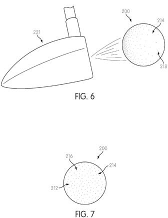
[0037] FIG. 5 shows ball 200 in its rest position just before it is struck by club 221. In FIG. 5, first pigment 212 is shown in its consolidated position on the bottom of ball 200. FIG. 6 shows ball 200 just after impact by club 221. As shown in FIG. 6, the impact of club 221 against ball 200 imparts a spin to ball 200. Regardless of which club is selected or how the ball is struck, it is highly likely that some sort of spin will be imparted to the ball. In many cases, the spin imparted to the ball will create a force on each pigment particle 216 in first pigment 212. This force may be a centrifugal force, in whole or in part. The force may be sufficient to cause one or more of pigment particles 216 to leave the consolidated position and move to a dispersed position, as is shown by an exemplary pigment particle 218 visible through outer layer 204 among the particles of second pigment 214.
[0038] FIG. 7 shows ball 200 after the first pigment 212 and first pigment particles 216 have reached a dispersed position. The density and evenness of the distribution of first pigment particles 216 relative to particles of second pigment 214 measure the amount of spin imparted to ball 200 by the stroke of club 221. This measurement indicates to a golfer how much spin is applied or imparted to ball 200 by his or her stroke. Once ball 200 finishes its flight and roll after the stroke, first pigment 212 returns to the consolidated position shown in FIG. 4 after an effective length of time. The effective length of time will vary depending on factors such as the relative density of the first pigment and the second pigment, the amount of spin imparted to the ball, and the air temperature. These factors are not exclusive, but will depend on other factors as well.
[0039] The remaining FIGS. (FIGS. 8-13) show other varying embodiments. Each of these embodiments shows a first pigment that settles to the bottom of a cavity or cavity portion similar to the embodiment shown in FIGS. 4-7. However, in any or all of these embodiments, the first pigment could instead be attracted to the inner layer, as shown in FIGS. 1-3. In addition, in any of these embodiments, some pigments may be selected to be attracted to the inner layer in some cavity sections and others to settle to the bottom of the cavity in other cavity sections. The placement of the pigments in the cavities and the precise formulation is left what a designer believes is useful or desirable.
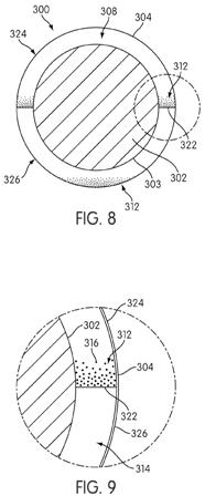
[0040] FIG. 8 shows a cross section of another embodiment of a golf ball 300. Golf ball 300 has a series of radially or circumferentially arranged layers. The innermost layer is core 302. Core 302 has the same properties as described above in connection with core 102 and inner layer 303 has the same properties as described above in connection with inner layer 103. Top or outer layer 304 is radially or circumferentially outward of inner layer 303 and has the same properties as described above in connection with outer layer 104. Inner layer 303 and outer layer 304 are spaced from one another and a space or cavity 308 is between the inner layer 303 and outer layer 304. A fluid may be present in cavity 308.
[0041] As shown in FIG. 8, it may be desirable in some embodiments to include divider 322 in ball 300 extending between inner layer 303 and outer layer 304. Divider 322 is shown in FIG. 8 as being annular and placed around a circumference of ball 300. Divider 322 divides cavity 308 into two substantially equal portions, specifically, first cavity portion 324 and second cavity portion 326. The use of a divider need not so separate cavity 308 and may instead separate cavity 308 into two dissimilarly sized portions. In addition, a divider could instead be used that is localized in a particular point or region and does not function as a divider. The divider may be considered to be a separator, separating the cavity into a plurality of spaces or separating the inner layer from the outer layer. FIG. 8 shows one possible rest position of ball 300; if ball 300 fell at a different angle to the ground, divider 322 would be positioned at a different angle relative to the ground.
[0042] FIG. 9 is a closer view of one portion of ball 300. FIGS. 8 and 9 show the use of first pigment 312 and second pigment 314. First pigment 312 and second pigment 314 have the same properties as described above in connection with first pigment 112 and second pigment 114, respectively. In FIGS. 8 and 9, ball 300 is in a rest position and first pigment 312 has settled to the bottom of each of first cavity portion 324 and second cavity portion 326 in its consolidated position. Among the reasons pigment particles 316 of first pigment 312 may settle to the bottom of first cavity portion 324 and second cavity portion 326 is if first pigment particles 316 on average are of a higher density or weight than particles of second pigment 314. When ball 300 is struck, first pigment particles 316 will disperse more evenly into second pigment 314 in a dispersed position. The greater weight or density of first pigment 312 may cause the first pigment to be more greatly affected by the spin and to disperse more towards outer layer 304, causing them to be visible over a greater portion of outer layer 304. When ball 300 comes to its next rest position, first pigment 312 will again settle to the bottom of each of first cavity portion 324 and second cavity portion 326.
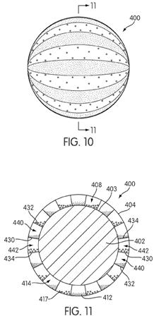
[0043] FIGS. 10 and 11 show another embodiment of a golf ball 400. FIG. 10 shows a plan view of golf ball 400 with pigments in a dispersed position, while FIG. 11 shows a cross section of golf ball 400 with pigments in a consolidated position. Golf ball 400 has a series of radially or circumferentially arranged layers. The innermost layer is core 402. Core 402 has the same properties as described above in connection with core 102 and inner layer 403 has the same properties as described above in connection with inner layer 103. Top or outer layer 404 is radially or circumferentially outward of inner layer 403 and has the same properties as described above in connection with outer layer 104. Inner layer 403 and outer layer 404 are spaced from one another and a space or cavity 408 is between inner layer 403 and outer layer 404. A fluid may be present in th
e cavity 408.
[0044] As shown most clearly in FIG. 11, it may be desirable in some embodiments to include a plurality of dividers in ball 400 extending between inner layer 403 and outer layer 404. First divider 430 is shown in FIG. 11 as being annular and placed around a circumference of ball 400. Second divider 432 is annular and spaced from and adjacent to first divider 430. Third divider 434 is annular and spaced from and adjacent to first divider 430 and on the opposite side of first divider 430 from second divider 432. In the embodiment shown in FIGS. 10 and 11, a plurality of equally spaced dividers is shown. First divider 430, second divider 432, and third divider 434 divide cavity 408 into portions, including first cavity portion 440 and second cavity portion 442. Each pair of adjacent dividers similarly provides a cavity portion therebetween in the embodiment shown in FIGS. 10 and 11. FIG. 11 shows one possible rest position of ball 400.
[0045] FIGS. 10 and 11 show the use of first pigment 412, second pigment 414, and third pigment 417. First pigment 412 and third pigment 417 generally have the same properties as described above in connection with first pigment 112. Second pigment 414 generally has the same properties as described above in connection with second pigment 114. In FIG. 11, ball 400 is in a rest position and first pigment 412 and third pigment 417 have settled to the bottom of each of first cavity portion 440 and second cavity portion 442, respectively, in a consolidated position. First pigment 412 is on a first side of divider 430 and third pigment 417 is on a second side of divider 430. Similarly, first pigment 412 is on a first side of divider 432 and third pigment 417 is on a second side of divider 432. Among the reasons pigment particles of first pigment 412 may settle to the bottom of first cavity portion 440 and third pigment 417 may settle to the bottom of the second cavity portion 442 is if pigment particles of first pigment 412 and third pigment 417 on average are of a higher density or weight than particles of second pigment 414. When ball 400 is struck, pigment particles of first pigment 412 and third pigment 417 will disperse more evenly into second pigment 414 in a dispersed position, such as that shown in FIG. 10. The greater weight or density of first pigment 412 and third pigment 417 may cause the first pigment and third pigment to be more greatly affected by the spin and to disperse more towards outer layer 404, possibly due in whole or in part to centrifugal force, causing them to be visible over a greater portion of outer layer 404. When ball 400 comes to its next rest position, first pigment 412 will again settle to the bottom of first cavity portion 440 and third pigment 417 will again settle to the bottom of second cavity portion 442.
[0046] FIG. 10 shows a striped pattern that may emerge when first pigment 412 and third pigment 417 are spun outwardly to a dispersed position, possibly created entirely or in part by centrifugal force by the rotation of the ball due to backspin. The use of such a pattern may allow ball 400 to have a reduced wait time before it may be struck again. When a ball having no dividers is used, the first pigment must return to a rest position without a boundary, which may be traveling a significant portion of the diameter of the ball without a diameter. When a divider is used, the pigment may only need to travel a short distance to return to a consolidated position. The use of a striped pattern may also be useful to determine spin more accurately. First pigment 412 may have a first color, second pigment 414 may have a second color, and third pigment 417 may have a third color. The first color, second color, and third color may all be different from one another. The first color and the third color may be generally primary colors that combine to form a secondary color. For example, the first color could be blue and the third color could be yellow, which would form green. The color visible to the eye would vary depending on the spin of the ball and the varying weights of the pigments. For example, a more blue-green could indicate a particular type of spin, while a yellow-green could indicate a different type of spin. This information may be useful to a golfer in changing stroke characteristics.
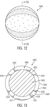
[0047] FIGS. 12 and 13 show another embodiment of a golf ball 500. FIG. 12 shows a plan view of golf ball 500 with pigments in a dispersed position, while FIG. 13 shows a cross section of golf ball 500 with pigments in a consolidated position. Golf ball 500 has a series of radially or circumferentially arranged layers. The innermost layer is core 502. Core 502 has the same properties as described above in connection with core 102 and inner layer 503 has the same properties as described above in connection with inner layer 103. Top or outer layer 504 is radially or circumferentially outward of inner layer 503 and has the same properties as described above in connection with outer layer 104. Inner layer 503 and outer layer 504 are spaced from one another and a space or cavity 508 is between inner layer 503 and outer layer 504. A fluid may be present in the cavity 508.
.
.
.
[0049] FIGS. 12 and 13 show the use of first pigment 512, second pigment 514, and third pigment 517. First pigment 512 and third pigment 517 generally have the same properties as described above in connection with first pigment 112. Second pigment 514 generally has the same properties as described above in connection with second pigment 114. In FIG. 13, ball 500 is in a rest position and first pigment 512 and third pigment 517 have settled to the bottom of each of first cavity portion 560 and second cavity portion 562, respectively, in a consolidated position. First pigment 512 is on a first side of divider 550 and third pigment 517 is on a second side of divider 550. Similarly, first pigment 512 is on a first side of divider 552 and third pigment 517 is on a second side of divider 552. Among the reasons pigment particles of first pigment 512 may settle to the bottom of first cavity portion 560 and third pigment 517 may settle to the bottom of second cavity portion 562 is if pigment particles of first pigment 512 and third pigment 517 on average are of a higher density or weight than particles of second pigment 514. When ball 500 is struck, pigment particles of first pigment 512 and third pigment 517 will disperse more evenly into the second pigment 514 in a dispersed position, such as that shown in FIG. 12. The greater weight or density of first pigment 512 and third pigment 517 may cause the first pigment and third pigment to be more greatly affected by the spin and to disperse more towards outer layer 504, possibly due in whole or in part to centrifugal force, causing them to be visible along a greater portion of outer layer 504. When ball 500 comes to its next rest position, first pigment 512 will again settle to the bottom of first cavity portion 560 and third pigment 517 will again settle to the bottom of third cavity portion 562.
Amazing! Sign me up for a few dozen.
David Dawsey – Keeping an Eye on Golf Ball Inventions