
Will We Ever See this PING Driver?
Check out the PING driver design disclosed in a patent application that published this week as US Pub. No. 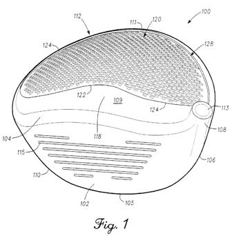
The application explains:
BACKGROUND
[0003] A golf club head, and in particular the crown of the golf club head, may be divided into several regions for purposes of illustrating the effects of forces generated by the impact of a golf ball against the face of the golf club head. The first region is in communication with the impact surface defined by the face of the golf club head such that the impact of a golf ball at the face directly causes internal stresses to be generated by the impact force of the golf ball that travels through and directly affects the first region of the crown. In addition, a second region of the golf club head may be defined along the crown between the first region and the back of the golf club head such that relatively lower stress and vibration should be felt in the second region by the forces generated after the impact of a golf ball against the face in comparison to the first region of the golf club head.
[0004] Many golf club heads are formed with a number of relatively large apertures defined along the second region of the crown in order to lessen the weight of the golf club head and/or change its center of gravity. However, this arrangement of large apertures can cause a disproportionate or uneven distribution of internal stresses through the second region of the crown when a golf ball strikes the face of the golf club head. In particular, stress risers, which are pockets of concentrated stress, can develop in the material of the crown between the apertures. Stress risers are caused when internal stresses generated by the impact force of a golf ball are distributed unevenly through the second region of the crown and focused on particular portions of the golf club head. This disproportional distribution of internal stresses through the second region of the crown can cause the structural failure of the golf club head over time as the area between the apertures crack or otherwise fail because of the excessive internal stresses being generated in the second region of the crown due to the bending forces being focused on a particular area of the crown after repeated impacts with a golf ball.
.
.
.
[0037] A golf club head may be divided into several regions for purposes of illustrating the effects of forces generated by the impact of a golf ball against face of the golf club head. As noted above, the first region is in communication with the impact surface defined by the face of the golf club head such that the impact of a golf ball at the face directly causes internal stresses generated by the force of the impact with the golf ball to travel through and directly affect the first region of the golf club head. A second region of the golf club head may be defined between the first region and the back of the golf club head such that a relatively lower stress and vibration are experienced in the second region by the forces generated after the impact of a golf ball against the face in comparison to the first region.[0038] Referring to the drawings, an embodiment of a golf club head is illustrated and generally indicated as 100 in FIG. 1. In general, the golf club head 100 may include a face 102, a sole 105, a heel 106, a toe 110, and a plurality of grooves 115. The golf club head 100 may be a single piece or include multiple portions manufactured together. In one example, the golf club head 100 may be a hollow body formed by a casting process or other suitable type of manufacturing process. In addition, the face 102 may be an integral part of the golf club head 100. Alternatively, the face 102 may be a separate piece from or an insert for a body of the golf club head 100.
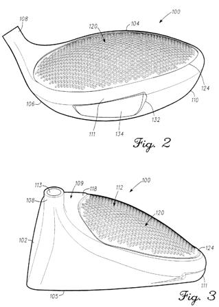
[0039] The golf club head 100 includes a hosel 108 that defines an aperture 113 configured to engage a shaft (not shown). In particular, the shaft may engage the golf club head 100 on one end and engage a grip (not shown) on an opposite end. For example, the golf club head 100 may be a wood-type golf club, such as a driver-type golf club head, a fairway wood-type golf club head (e.g., 2-wood golf club, 3-wood golf club, 4-wood golf club, 5-wood golf club, 6-wood golf club, 7-wood golf club, 8-wood golf club, or a 9-wood golf club), a hybrid-type golf club head or any other suitable type of golf club head with a hollow body or a body with one or more cavities, apertures, recesses or channels. Although the above examples may depict and/or describe a wood-type golf club head (e.g. driver-type golf club head, a fairway-type golf club head, a hybrid-type golf club head), the apparatus, articles of manufacture, and methods described herein may be applicable to other suitable types of golf club heads.
[0040] In addition, the face 102 may be formed adjacent the hosel 108 and provides a surface for striking a golf ball (not shown). The face 102 may be made from one or more metals or metal alloys such as a steel material, a titanium material, a titanium alloy material, a titanium-based material, a combination thereof, one or more composite materials, one or more plastic materials, or other suitable type of materials: however, the face 102 may be made from the same material(s) that constitute the golf club head 100 as described in greater detail below. In particular, the face 102 may include a plurality of grooves, generally shown as 115 in FIG. 1. The golf club head 100 further includes a back 111 formed opposite the face 102 with the sole 105 being defined between the back 111 and the face 102. As further shown, a crown 109 is formed opposite the sole 105, while the face 102 is defined by the heel 106 formed adjacent the hosel 108 and the toe 110 defined at the far end of the face 102. The face 102 further includes a top edge 104 defined between the crown 109 and the face 102 as well as a leading edge 103 defined between the sole 105 and the face 102. In one embodiment, the back 111 may define a cavity 132 configured to receive an insert 134 in order to change the center of gravity and the moment of inertia of the golf club head 100: however, the apparatus, articles of manufacture, and methods described herein are not limited in this regard. Although the golf club head 100 may conform to rules and/or standards of golf defined by various golf standard organizations, governing bodies, and/or rule establishing entities, the apparatus, articles of manufacture, and methods described herein are not limited in this regard.
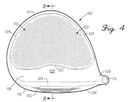
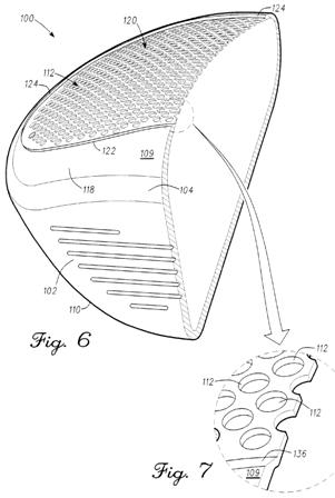
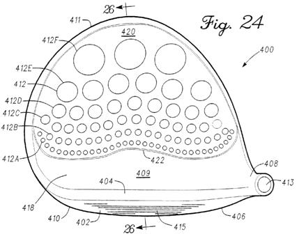
[0041] Referring to FIG. 9, in one embodiment the crown 109 may include a first region 118 and a s
econd region 120 with a bell-shaped curve 122 that may define the boundary between the first and second regions 118 and 120. Details of the bell-shaped curve are provided in U.S. Pat. No. 7,892,111, the entire disclosure of which is incorporated by reference. The first region 118 may sustain and endure relatively more stress than the second region 120 in response to an impact on the face 102 of the golf club head 100 by an object such as a golf ball (not shown). In one example, the bell-shaped curve 122 may include a first point 125, a second point 126 and a third point 127. The first point 125 may be located at or proximate the toe 110 of the golf club head 100, while the second point 126 may be located at or proximate the heel 106 of the golf club head 100. The third point 127 may be located at or proximate a midpoint defined between the first and second points 125 and 126 with the third point 127 being defined closer to the back 111 of the golf club head 100 than first and second points 125 and 126.[0042] As shown in FIG. 8, the bell-shaped curve 122 that defines the boundary between the first and second regions 118 and 120 of the crown 109 may be determined by the relationship between a loft angle 114 of the face 102 and a first plane 116 separated by a predetermined distance D1. In one embodiment, the predetermined distance D1 may be defined as the distance between the top edge 104 of the face 102 and the first plane 116 at the location where first plane 116 intersects the crown 109. For example, the predetermined distance D1 may be greater than one inch. Alternatively, the predetermined distance D1 may be defined as the distance between the leading edge 103 of the face 102 and the location of the first plane 116 where the first plane 116 intersects the sole 105. In addition, the position of the first plane 116 may be established by the orientation or angle of the loft angle 114 of the golf club head 100. In one embodiment, the loft angle 114 may be established by the angle of the face 102 for a particular golf club head 100. For example, the loft angle 114 for a driver-type golf club head may range between 6.degree. to 16.degree., while the loft angle 114 for a fairway-type golf club head may range between 12.degree. to 30.degree.. The loft angle 114 for a hybrid-type golf club head may range between 16.degree. to 34.degree.. As such, the location of the bell-shaped curve 122 along the crown 109, may be determined by the intersection of the first plane 116 with the crown 109 to establish the location of either the first and second points 125 and 126 (FIG. 9), or the third point 127 of the bell-shaped curve 122.
Looks interesting, but it is hard to imagine that this will make it into a commercial product.