
When You are Teeing Off Do You Really Want to Stare Down at a Club Head Having a Diagram of the CG Location?
I would bet the answer for 99% of golfers the answer is a resounding NO. Apparently Bridgestone Golf disagrees because one of their recently published patent applications is directed to just that, a CG map on the crown of a golf club. The application published as US Pub. No. 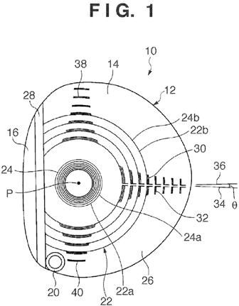
The application goes on to explain:
[0008] It is an object of the present invention to provide a wood type golf club head that allows the golfer to readily pay attention to the head’s center-of-gravity position.
[0009] According to an aspect of the present invention, there is provided a wood type golf club head including a face portion and a crown portion, wherein a center-of-gravity position mark which indicates a point where a center of gravity of the wood type golf club head is projected to the crown portion is formed on a surface of the crown portion.
[0010] According to another aspect of the present invention, there is provided a wood type golf club head including a face portion, wherein a center-of-gravity position mark which indicates a point where a center of gravity of the wood type golf club head is projected to the face portion is formed in the face portion by one of a blasting method and a YAG laser irradiation method.
[0011] According to still another aspect of the present invention, there is provided a wood type golf club head including a face portion and a crown portion, wherein a first center-of-gravity position mark which indicates a point where a center of gravity of the wood type golf club head is projected to the crown portion is formed on a surface of the crown portion, and a second center-of-gravity position mark which indicates a point where the center of gravity is projected to the face portion is formed in the face portion.
.
.
.
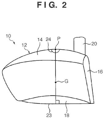
[0024] In the golf club head 10 according to this embodiment, a visible center-of-gravity position mark 22 which indicates a point P where a head’s center of gravity G is projected to the crown portion 14 is formed on the surface of the crown portion 14. The point P is a small region that is or includes a point where a straight line which is perpendicular to a sole surface 23 and passes through the center of gravity G intersects with the crown portion 14. The center-of-gravity position mark 22 includes a plurality of concentric circles 24 with the point P as a center.[0025] More specifically, the center-of-gravity position mark 22 includes an inner concentric circle arrangement portion 22a and outer concentric circle arrangement portion 22b. In the inner concentric circle arrangement portion 22a, a plurality of concentric circles 24a which have small diameters and the point P as a center are formed at a short interval. In the outer concentric circle arrangement portion 22b, a plurality of concentric circles 24b which have large diameters and the point P as a center are formed at a slightly long interval. In this case, the innermost circle 24 of the center-of-gravity position mark 22 surrounds the position of the point P, where the head’s center of gravity G is projected to the crown portion 14, when the golf club head 10 is set at a lie angle of 57.degree. to 63.degree.. This is because a driver head generally has a lie angle of around 60.degree., and this means that by setting the point P when the golfer addresses a ball at a lie angle of 57.degree. to 63.degree. to fall within the innermost circle 24, the center-of-gravity position mark 22 allows many golfers to pay attention to the center-of-gravity position. The diameter of the innermost circle 24 is preferably within a range of 5 mm to 25 mm. A more preferable value of the diameter of the innermost circle 24 is 17 mm. The innermost circle 24 may be a hollow or filled circle.
[0026] The center-of-gravity position mark 22 according to this embodiment allows the golfer to pay attention to the point P, which is the center of the plurality of concentric circles 24, as a center-of-gravity position. Note that although the point P is indicated by filled circles in FIGS. 1 and 2, no mark which indicates the point P itself is inscribed on an actual club. Note also that FIG. 2 shows only the innermost circle 24 of the center-of-gravity position mark 22.
[0027] In the golf club head 10 according to this embodiment, the crown portion 14 has, in portions other than its face-side edge, a colored portion 26 painted in colors such as black, blue, green, gray, or red as needed, and has, in its face-side edge, an uncolored portion 28 which is not colored and therefore has its metal exposed from it. The colored portion 26 is colored such that the color is lightest in the vicinity of the point P and gradually darkens outward.
[0028] Since this coloring configuration also features the center-of-gravity position mark in the present invention, it allows the golfer to pay attention to the portion with the lightest color as a center-of-gravity position. Note that the uncolored portion 28 in which the metal is exposed is provided in the face-side edge of the crown portion 14 in order to match the color of the uncolored portion 28 with that of the face portion 16. Thus, the face portion 16 shows its large area to the golfer upon address, thereby giving a sense of reassurance to him or her.
[0029] In the golf club head 10 according to this embodiment, a take-back line mark 30 which indicates the take-back direction is formed on the surface of the crown portion 14 in the back direction using the outer edge of the inner concentric circle arrangement portion 22a of the center-of-gravity position mark 22 as a base point. The take-back line mark 30 is formed by aligning roughly L-shaped patterns 32 along a precise take-back line, and the patterns 32 get smaller toward the back side. Also, since the golf club head 10 according to this embodiment is a hook face head, the angle .theta. between a center line 34 of the take-back line mark 30, and a straight line 36 perpendicular to the face surface is 1.degree. to 5.degree. and preferably is 2.degree. to 4.degree..
[0030] In the golf club head 10 according to this embodiment, a toe-to-heel line mark 38 which indicates the toe-to-heel direction is formed on the surface of the crown portion 14. The toe-to-heel line mark 38 includes a toe-side mark 38a extending in the toe direction using the outer edge of the inner concentric circle arrangement portion 22a of the center-of-gravity position mark 22 as a base point, and a heel-side mark 38b extending in the heel direction using that outer edge as a base point. The toe-to-heel line mark 38 is formed by aligning arcuated patterns 40 in the toe-to-heel direction, and the patterns 40 get smaller toward the toe and heel sides. The toe-to-heel line mark 38 is formed aiming to, for example, allow the golfer to notice the center-of-gravity position in the toe-to-heel direction, allow him or her to pay careful attention to the center-of-gravity position, accentuate a feeling of square upon address, and improve the design performance.
[0031] In the golf club head 10 according to this embodiment, the center-of-gravity position mark 22, take-back line mark 30, and toe-to-heel line mark 38 are formed by creating the concentric circles 24, roughly L-shaped patterns 32, and
arcuated patterns 40 with line widths of 0.1 to 0.5 mm using a method of scraping off the paint with laser light (burn-off). However, the pattern forming method is not limited to this, and these patterns can be formed using a method such as transfer sealing (water transfer), selective painting, or blasting.[0032] The golf club head 10 according to this embodiment allows the golfer to focus attention on the head’s center-of-gravity position and the take-back direction using a combination of colors or patterns, and therefore allows him or her to have a stable swing.
So, do you think this club will make it into the bag of Mr. Couples?
Dave Dawsey – Keeping an Eye on Innovative Golf Products
PS – check out some interesting golf tee inventions here