
What’s Behind PING’s Craz-D Optigraphic Alignment Aid?
Last week a patent application published that is directed to the PING’s Craz-D Optigraphic Alignment Aid (view HERE and HERE). I have never tried one of these putters but they look interesting, and with a fancy name like that there must be some cool science involved. Right?
The patent application published as US Pub. No. 20090270196 titled “Golf Club Head with a Three-Dimensional Alignment Member and Methods to Manufacture Golf Club Heads.” The application explains:
[0003] The performance of an individual may be enhanced by improving alignment of a golf club head relative to a golf ball at an address position. For instance, proper alignment between the golf club head and the golf ball may result in better control over the distance, direction, spin, and/or speed of the golf ball. Conversely, an off-center impact may result without proper alignment between the golf club head and the golf ball. An off-center impact may occur if the golf ball contacts the striking face of the golf club head at or proximate to the heel end or the toe end of the striking face. To avoid an off-center impact, the individual may direct his or her vision over the golf club head to improve alignment between the golf club head and the golf ball. To ease and improve the individual’s visual alignment, various alignment features may be included on the golf club head.
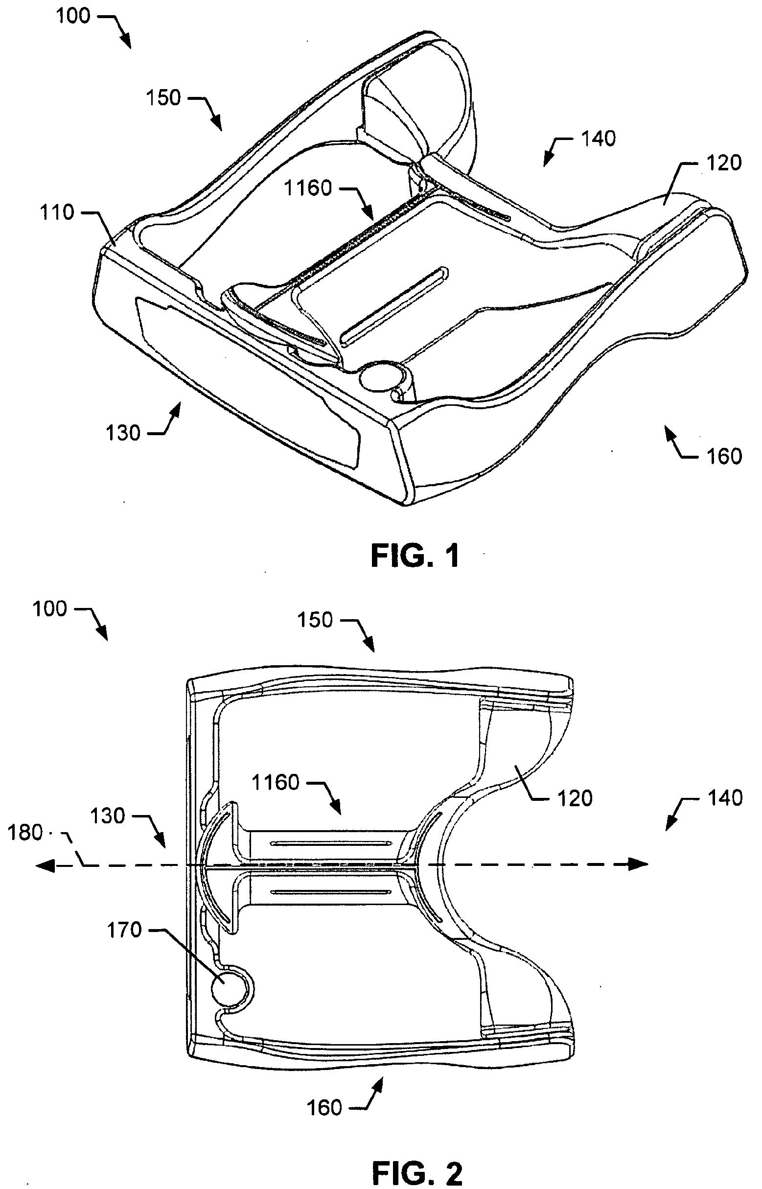
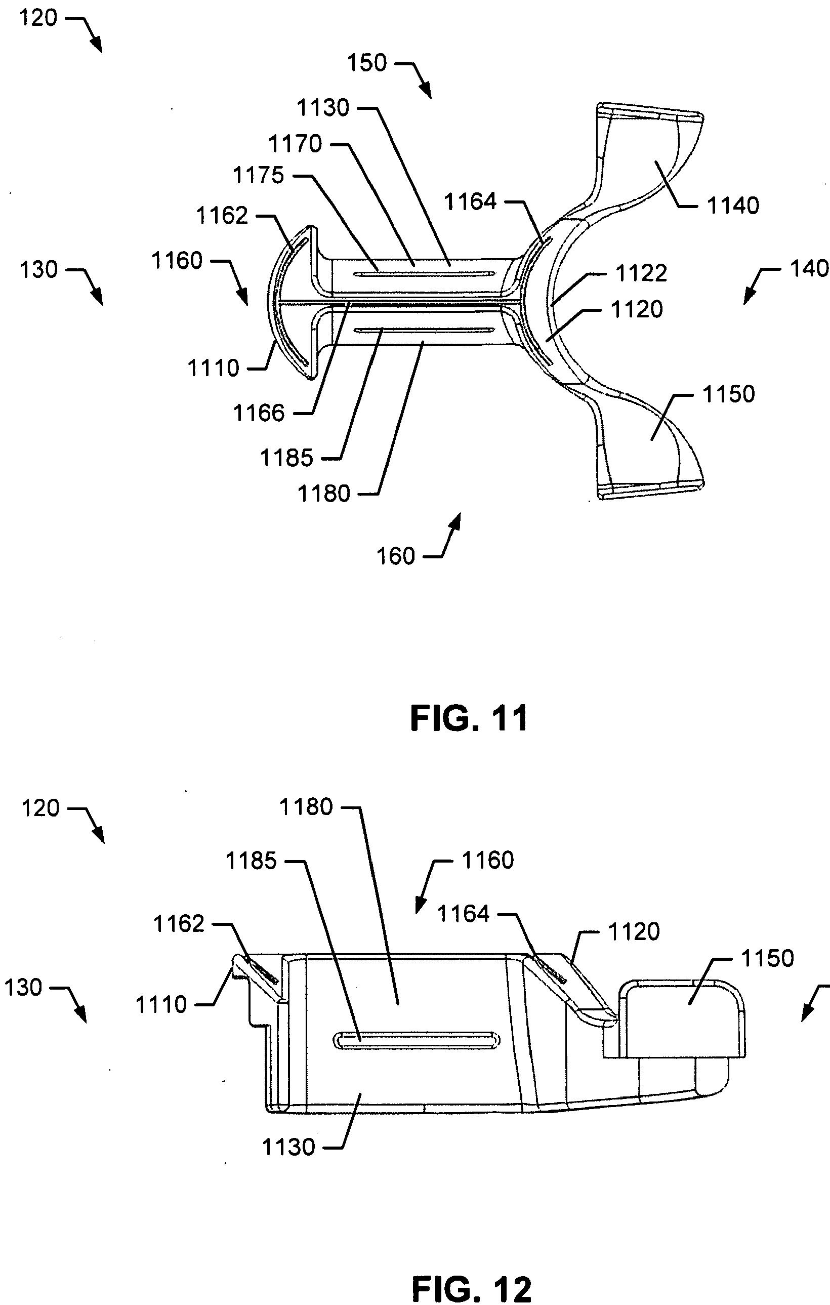
[0048] The straight section 1166 may be located on, or integral to, the central portion 1130. Further, the straight section 1166 may be positioned between the first and second arc sections 1162 and 1164. In particular, the straight section 1166 may connect the first arc section 1162 and the second arc section 1164. The first arc section 1162, the second arc section 1164, and the straight section 1166 may be sunken sections on the second body portion 120. However, each of the sections of the visual alignment member 1160 may include a raised section, a line, a colored section, or any combination thereof, and/or other suitable types of markings.
[0049] The central portion 1130 may include a first side wall 1170 and a second side wall 1180. In one example, the visual alignment member 1160 may also include side wall straight sections, generally shown as 1175 and 1185, on each of the first and second side walls 1170 and 1180, respectively. All sections of the visual alignment member 1160 may be visible to an individual (e.g., the first arc section 1162, the second arc section 1164, the straight section 1166, the first side wall straight section 1175, and the second side wall straight section 1185). For instance, the visual alignment member 1160 may be visible to an individual when the golf club head 100 is positioned to properly address the golf ball 1600. Accordingly, an individual may have better control over the distance, direction, spin, and/or speed of the golf ball 1600.
[0050] Further, the second body portion 120 may include one or more cavities, generally shown as a first cavity 1190 and a second cavity 1195. The first cavity 1190 may be associated with the first leg portion 1140 whereas the second cavity 1195 may be associated with the second leg portion 1150. One or more removable weights (not shown) may be disposed in each of the first cavity 1190 and the second cavity 1195. Although the figures may depict the first and second cavities 1190 and 1195 as circular cavities, the first and second cavities 1190 and 1195 may have other suitable shapes (e.g., oval, elliptical, triangular, square, rectangular, etc.).
[0051] The second body portion 120 may be coupled to the first body portion 110 to form the golf club head 100. In particular, the first arcuate portion 1110 of the second body portion 120 may be coupled to a back side 1035 (FIG. 10) of the face portion 730 of the first body portion 110. Further, the first and second leg portions 1140 and 1150 may be coupled to the first and second arm portions 710 and 720, respectively, at the back end 140 of the first body portion 110. The second body portion 120 may be secured to the first body portion 110 by one or more fasteners, generally shown as 310, 320, and 330 (FIG. 3). In addition or alternatively, the first and second body portions 110 and 120 may be coupled together by other suitable manners (e.g., adhesive). The methods, apparatus, and articles of manufacture are not limited in this regard.
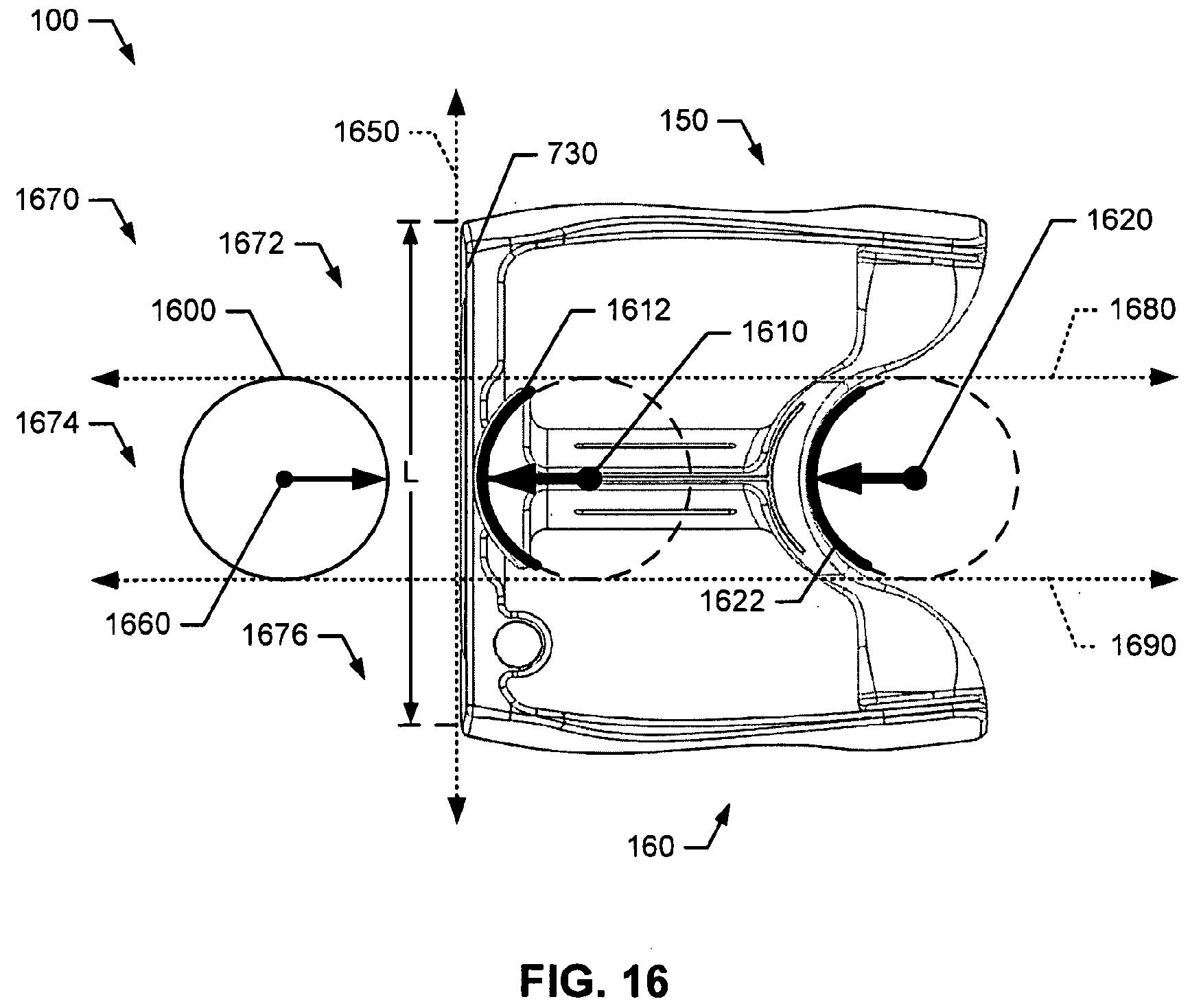
[0052] In the example of FIGS. 16-18, the first and second arcuate portions 1110 and 1120 of the golf club head 100 may be formed based on the dimensions of a golf ball 1600 as defined by golf standard organizations and/or governing bodies such as the United States Golf Association (USGA) and the Royal and Ancient Golf Club of St. Andrews (R&A). For example, the USGA may specify that the diameter of the golf ball 1600 is greater than 1.68 inches. The methods, apparatus, and articles of manufacture described herein are not limited in this regard.
[0053] As three-dimensional features, the first and second arcuate portions 1110 and 1120 may each have curvatures in the horizontal direction and the vertical direction. With respect to curvatures in the horizontal direction, the first arcuate portion 1110 may be associated with a first horizontal radius 1610 and a first horizontal arc 1612 relative to a first vertical plane 1650 (FIG. 16). The first vertical plane 1650 may extend between the toe end 150 and the heel end 160. Similarly, the second arcuate portion 1120 may be associated with a second horizontal radius 1620 and a second horizontal arc 1622 relatively to the first vertical plane 1650.
[0054] Both the first and second horizontal radii 1610 and 1620 may be substantially equivalent to the radius 1660 of the golf ball 1600. Accordingly, in one example, the first and second horizontal radii 1610 and 1620 may be about 0.84 inches. While the first and second horizontal arcs 1612 and 1622 may be similar in length, the arc lengths are not limited in this regard. For instance, the first horizontal arc 1612 may be longer or shorter than the second horizontal arc 1622. The methods, apparatus, and articles of manufacture are not limited in this regard.
[0055] With respect to curvature in the vertical direction, the first arcuate portion 1110 may be associated with a first vertical radius 1710 and a first vertical arc 1712 relative to a horizontal ground plane 1700 (FIGS. 17 and 18). The first arcuate portion 1110 may extend above the top rail 740 in the vertical direction. Similarly, the second arcuate portion 1120 may be associated with a second vertical radius 1810 and a second vertical arc 1812 relative to the horizontal ground plane 1700 (FIGS. 17 and 18). The second arcuate portion 1120 may also extend above the top rail 740 in the vertical direction. While the top rail 740 may be depicted as a substantially flat surface, the top rail 740 may also be an arcuate surface. For example, the top rail 740 may be an arcuate surface between the striking face 735 and the back side 1035.
[0056] Both the first and second vertical radii 1710 and 1810 may be substantially equivalent to the radius 1660 of the golf ball 1600. Accordingly, in one example, the first and second vertical radii 1710 and 1820 may be about 0.84 inches. While the first and second vertical arcs 1712 and 1812 may be similar in length, the arc lengths are not limited in this regard. For instance, the
first vertical arc 1712 may be longer or shorter than the second vertical arc 1812. The methods, apparatus, and articles of manufacture are not limited in this regard.[0057] Alternatively, the first and second arcuate portions 1110 and 1120 may be larger than the dimensions of the golf ball 1600. For example, as shown in FIG. 17, the first vertical radius 1710 may larger than the radius of a golf ball 1600. A larger first vertical radius 1710 may be associated with a longer first vertical arc 1712, generally shown as 1714 and 1716. The vertical arcs 1712, 1714, and 1716 may be concentric to each other. Similarly, the second vertical radius 1810 (FIG. 18) may be increased to a size greater than the radius of a golf ball 1660, resulting in a longer second vertical arc 1812.
[0058] Further, the golf club head 100 may comprise a plurality of regions 1670, generally shown as a toe region 1672, a middle region 1674, and a heel region 1676 as shown in FIGS. 16 and 18. The plurality of regions 1670 may be defined by a second vertical plane 1680 and a third vertical plane 1690. The second and third vertical planes 1680 and 1690 may be parallel to each other. The second and third vertical planes 1680 and 1690 may extend between the toe end 130 and the heel end 140. Further, the second and third vertical planes 1680 and 1690 may be normal to the ground plane 1700 (FIGS. 17 and 18) of the golf club head 100.
[0059] The second and third vertical planes 1680 and 1690 may divide the golf club head 100 into three similarly-sized regions. For example, the face portion 730 may have a horizontal length L between the toe end 150 and the heel end 160, and the second vertical plane 1680 may be positioned a distance of approximately (1/3)*L from the toe end 150. Similarly, the third vertical plane 1690 may positioned a distance of approximately (1/3)*L from the heel end 160. Accordingly, the second and third vertical planes 1680 and 1690 may be separated by a distance of approximately (1/3)*L.
Boy, I was hoping for something more intriguing than that. Oh well, I suppose 99% of patent application don’t make for edge-of-the-seat reading material.
PING is definitely cranking out the putter inventions as they had another alignment aid patent application publish last week as US Pub. No. 20090270198. Check it out.
David Dawsey – The Putter Patent Lawyer
PS – click here to check out putter alignment features that may not be quite as useful, and click here for another interesting alignment feature