
The New Nike Tour Ball Ball?
A recently published patent application gives us a sneak peek at what some may consider as a breakthrough in the field of backyard practice golf balls, if there is such a field. The Nike Golf patent application published as US Pub. No. Golf balls with a reduced flight path are disclosed. In some cases, foam incorporated into a middle layer increases impact absorption and reduces a ball’s flight path. In other cases, a dimple pattern may be selected to reduce a ball’s flight path. In other instances, a parachute or other drag inducer may be deployed as a result of striking the ball to induce drag and minimize the ball’s flight path.
Yes, you read that correctly, “a parachute or other drag inducer may be deployed.” Check it out.
The application goes on to explain:
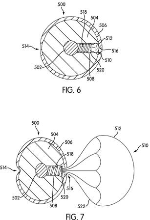
[0035] A cavity 508 is defined in middle layer 504 and is positioned between at least a portion of core 502 and at least a portion of cover 506. A drag inducer or dampener 510 is disposed in cavity 508. In FIGS. 6 and 7, drag inducer or dampener 510 comprises parachute 512. Parachute 512 is shown in FIG. 6 in a stored position and is shown in FIG. 7 in a deployed position.
[0036] Ball 500 includes parts that allow parachute 512 to move from its stored position to its deployed position. Ball 500 may include weakened area 514. Weakened area 514 on ball 500 takes the form of a region where cover 506 is thinned relative to the rest of cover 506. Instead of a thinning of cover 506, weakened area 514 could be weakened in other ways, such as by increasing the porosity of cover 506 in a particular area or by using a different material in weakened area 514 from the remainder of cover 506. Any method of weakening cover 506 in weakened area 514 may be appropriate for a given application. Opposite weakened area 514 is door 516. In FIGS. 6 and 7, door 516 takes the form of a split in cover 506 adjacent cavity 508. In FIG. 6, door 516 is in a closed position, and in FIG. 7, door 516 is in an open position. Door 516 moves from its closed position to its open position when force is applied about at weakened area 514. Upon application of force, ball 500 compresses and weakened area 514 may bend inwardly. This compression in weakened area 514 may be greater than the compression in the other areas of ball 500. The compression allows the halves of split or door 516 to move apart. The moving of door 516 from its closed position to its open position exposes parachute 512.[0037] When door 516 moves from its closed position to its open position and exposes parachute 512, a bias may be used to move parachute 512 from its stored position to its deployed position. The bias may be spring 518. Spring 518 may be positioned in cavity 508. One end of spring 518 may be secured or anchored to core 502, interior surface of cavity 508, or any other available location in ball 500. Alternatively, spring 518 may simply be placed within cavity 508. The opposite end of spring 518 may be secured or placed adjacent a first side of plate 520. When drag inducer 512 is in its stored position, spring 518 is compressed. The release of spring 518 causes the deployment of parachute 512. Plate 520 may be positioned between bias or spring 518 and drag inducer or parachute 512. First ends of strings 522 may be attached to a second side of plate 520. Alternatively, first ends of strings 522 may be secured in cavity 508 or in another part of ball 500. Second ends of strings 522 may be attached to parachute 512.
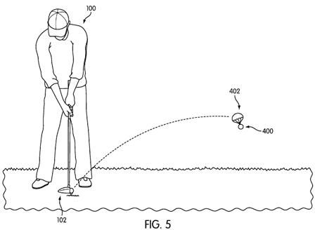
[0038] The deployment of parachute 512 may include a number of steps. First, a golfer strikes ball 500, desirably near weakened area 514. The striking of ball 500 causes the compression of ball 500, and causes an increased compression in weakened area 514. The increased compression in weakened area 514 creates a rotation of parts of cover 506 to open door 516 on the other side of ball 500. The opening of door 516 allows bias 518 to be released and press plate 520 outward towards door 516. The movement of bias 518 causes the pressing of drag inducer 512 outside of cover 506, deploying drag inducer 512. The deploying of parachute 512 creates drag on ball 500 and reduces the flight path of ball 500. In some instances, the materials, sizes, and shapes of the elements of ball 500 may be selected to minimize the flight path of ball 500 and reduce it to less than 100 yards.
[0039] Another embodiment using a parachute is shown in FIG. 8. Ball 600 includes a core 602, a middle layer 604, and a cover 606. Middle layer 604 is positioned radially outwardly from core 602 and at least partially surrounds core 602. Cover 606 is positioned radially outwardly from middle layer 604 and at least partially surrounds middle layer 604.
[0040] A cavity 608 is defined in middle layer 604 and is positioned between at least a portion of core 602 and at least a portion of cover 606. A drag inducer or dampener is disposed in cavity 608. In FIG. 8, the drag inducer or dampener comprises parachute 612. Parachute 612 is shown in FIG. 8 in a stored position.
[0041] Ball 600 includes parts that allow parachute 612 to move from its stored position to its deployed position. In one area on cover 606 is door 616. In FIG. 8, door 616 is shown in its closed position. Door 616 may be rotatably secured to cover 606 in any convenient manner. In some instances, it may be desirable to secure door 616 and cover 606 together in a manner and with a structure that presents a continuous surface. FIG. 8 shows the use of a living hinge 630 as the attachment structure.
[0042] It is desirable to use a structure to further secure door 616 and cover 606 together. For example, seal 624 can be positioned along one or more sides of the opening in cover 606 to hold door 616 in place.
Ridiculous? Yes. Would golfers buy a parachute golf ball to hit around the backyard? Absolutely.
David Dawsey – Keeping an Eye on Golf Ball Technology