
The Likely Callaway Jailbreak Technology
After a brief hiatus, I am back and ready to ruin the day of marketing departments across Carlsbad! I kid, somewhat – after all, I don’t know for sure that this is the secretive Callaway Epic “jailbreak” technology. Golf gear heads will know what I am referring to, however if you don’t, you may want to check out a few leaked photos here.
Just prior to the leaked photos a Callaway patent application published under the title “golf club head having stress-reducing features,” which happens to disclose a design with features suggesting it may be the new “jailbreak” technology. The patent application describes the invention as:
A golf club head comprising a body and a plurality of stiffening members is disclosed herein. The body comprises a face section, a sole section, and a crown section, and defines a hollow interior. Each of the plurality of stiffening members extends from the crown section to the sole section to reduce stresses placed on the face section during impact with a golf ball. The stiffening members are all located within 0.500 inch of a rear surface of the face section measured along a plane normal to the center of the face, and within 1 inch of the center of the face section along a horizontal axis parallel to the face section.
Humm, stiffening members to reduce face stress, tell me more.
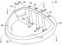
[0024] As shown in FIGS. 1-6, a preferred embodiment of the golf club head 10 of the present invention is generally designated. The golf club head 10 includes a body 20 having a sole section 22, a striking face section 30, a return section 32 extending away from an upper edge of the striking face section 30, a hosel 24 for engaging a shaft, a heel end 23, a toe end 25, an upper opening 26, a hollow interior 27, and an aft end 28. A crown section 40 is comprised of the return section 32 and a crown insert 42 that is placed over the upper opening 26 to enclose the hollow interior 27. Within the hollow interior 27, multiple stiffening members 50 (preferably two to eight) extend from the sole section 22 upward to the return section 32. In an alternative embodiment, the stiffening members 50 may extend to the crown insert 42 instead–what is important is that the stiffening members 50 connect the crown section 40 to the sole section 22.
[0025] As shown in FIG. 3, the preferred embodiment has three stiffening members 50a, 50b, 50c. Each of the stiffening members 50a, 50b, 50c in the preferred embodiment is a solid cylindrical rod composed of a lightweight, strong metal material such as titanium alloy or steel, though in an alternative embodiment the stiffening members 50a, 50b, 50c each may be a hollow tube made of a strong lightweight metal or a composite material. In another embodiment, the golf club head 10 may include one or more of both the solid rod and hollow tube types of stiffening members 50. In the preferred embodiment, each of the stiffening members 50 preferably has a diameter ranging from 0.050 inch to 0.200 inch and a length ranging from 1 to 2.5 inches. If any of the stiffening members 50 is a hollow tube, it preferably has a mass that ranges from 0.5 gram to 3 grams, more preferably from 1 gram to 2 grams, and most preferably 1.5 grams.
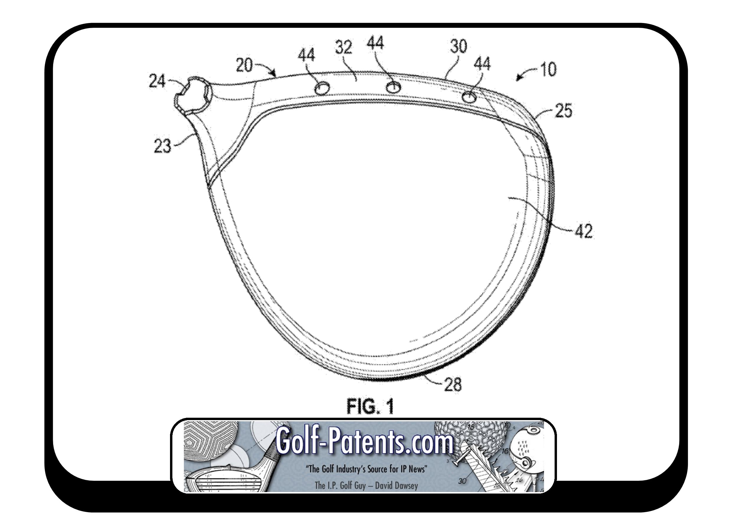


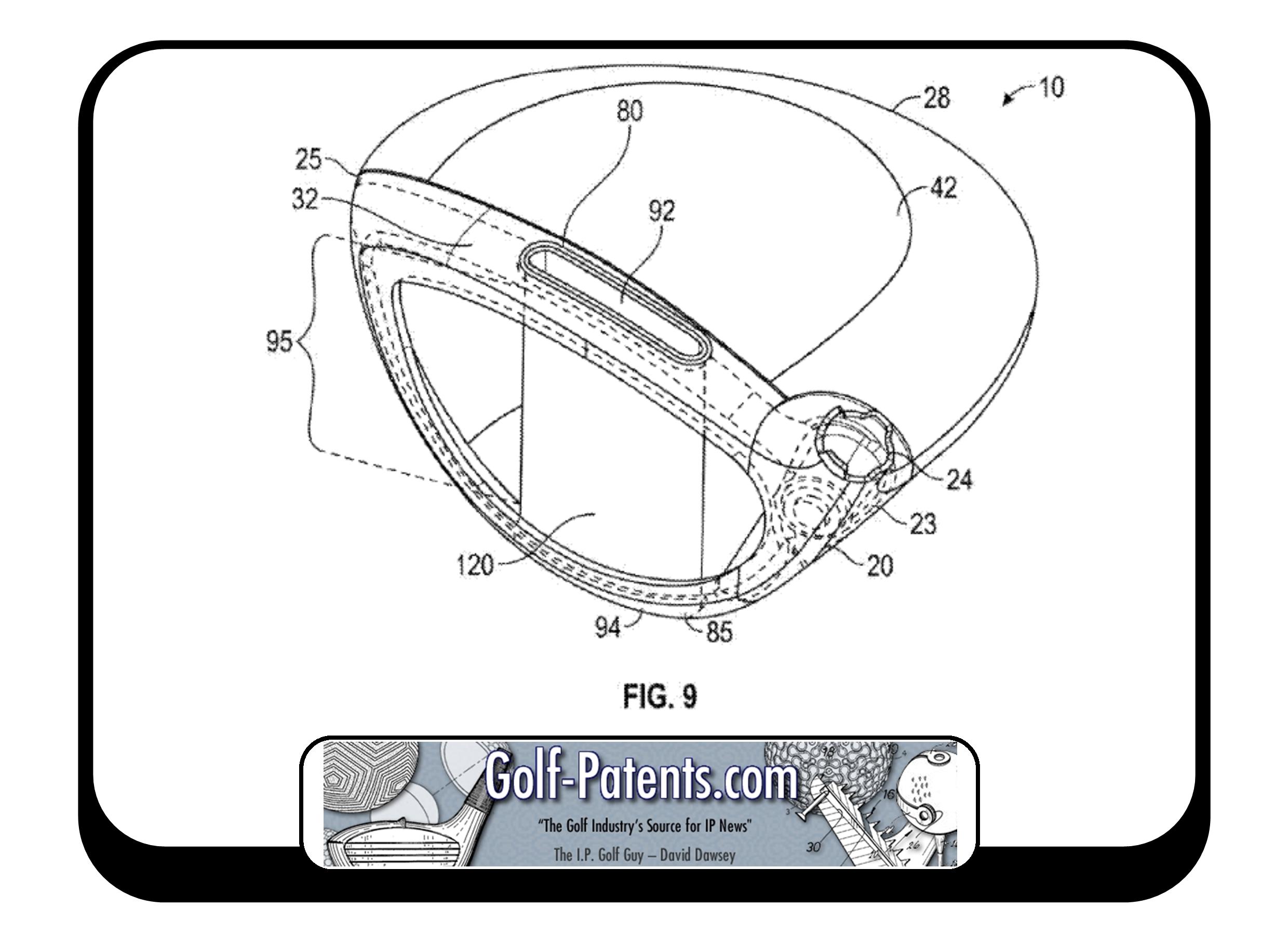
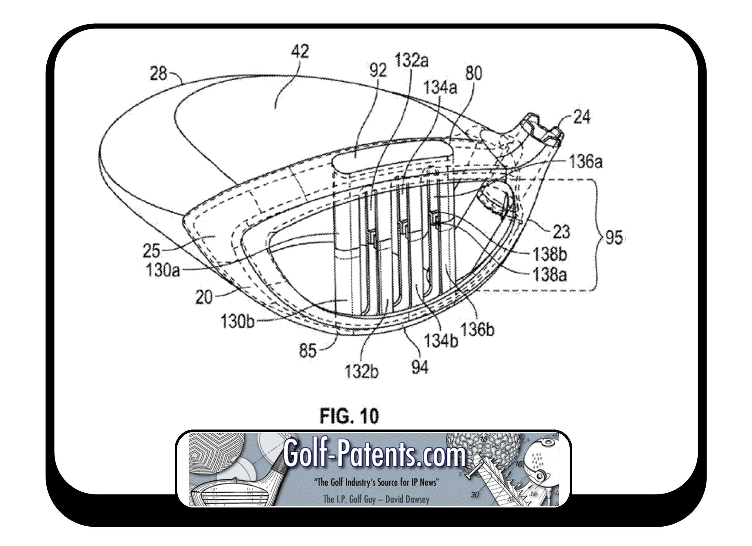
[0027] In alternative embodiments, shown in FIGS. 7-10, the golf club head 10 has each of the elements of the preferred embodiment, except that the return section 32 comprises a single upper aperture 80 and the sole section 22 comprises a single lower aperture 85 located directly opposite the upper aperture 80. The apertures 80, 85 are sized to receive upper and lower portions 92, 94, respectively, of an elongated cartridge 90 having a stiffening middle portion 95, examples of which are shown in these Figures. The elongated cartridge 90 preferably is removable, and may have locking features that reversibly affix the upper and lower portions 92, 94 to the body 20, but in other embodiments may be permanently affixed to the golf club head 10 via welding or bonding.
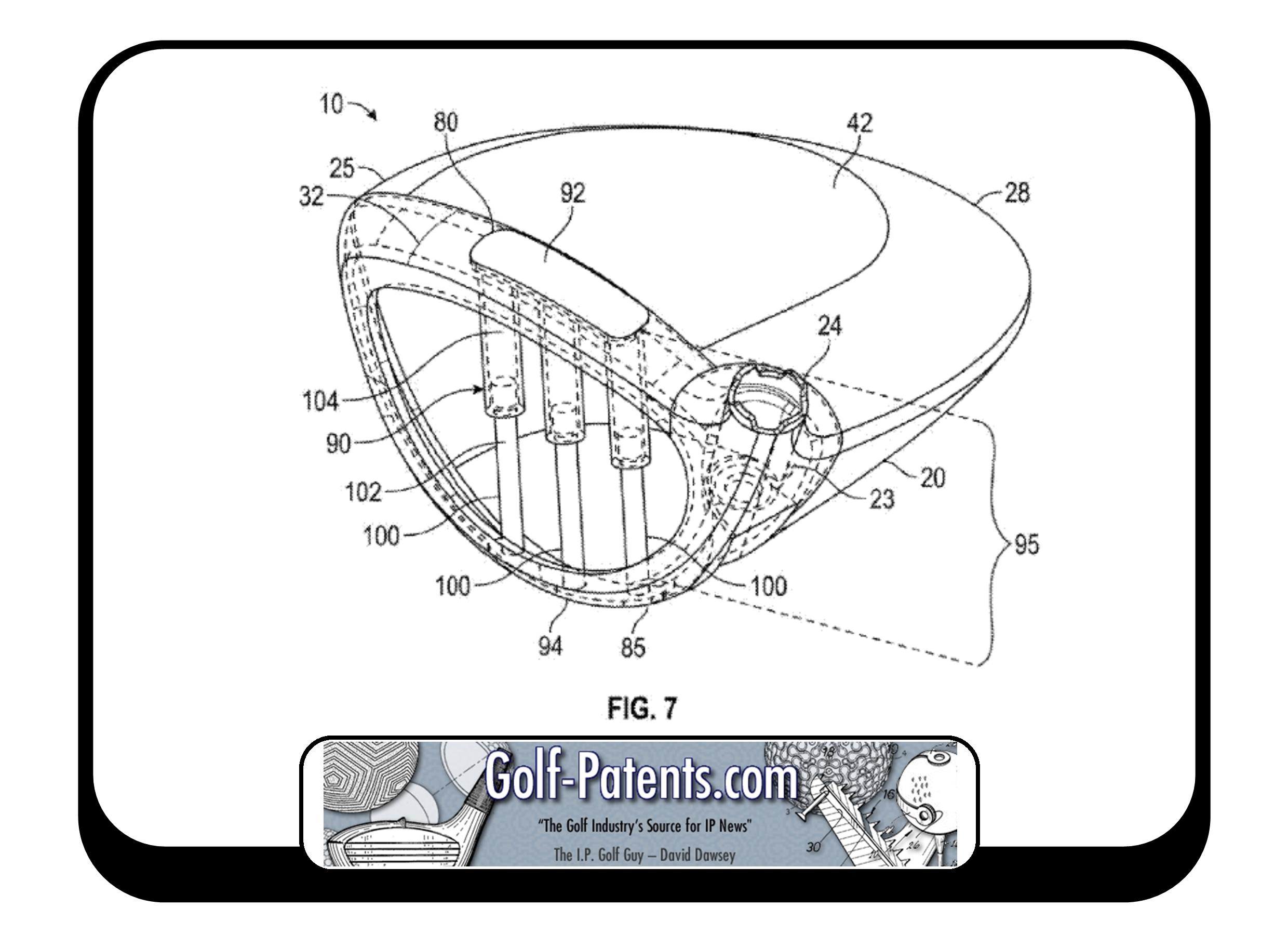
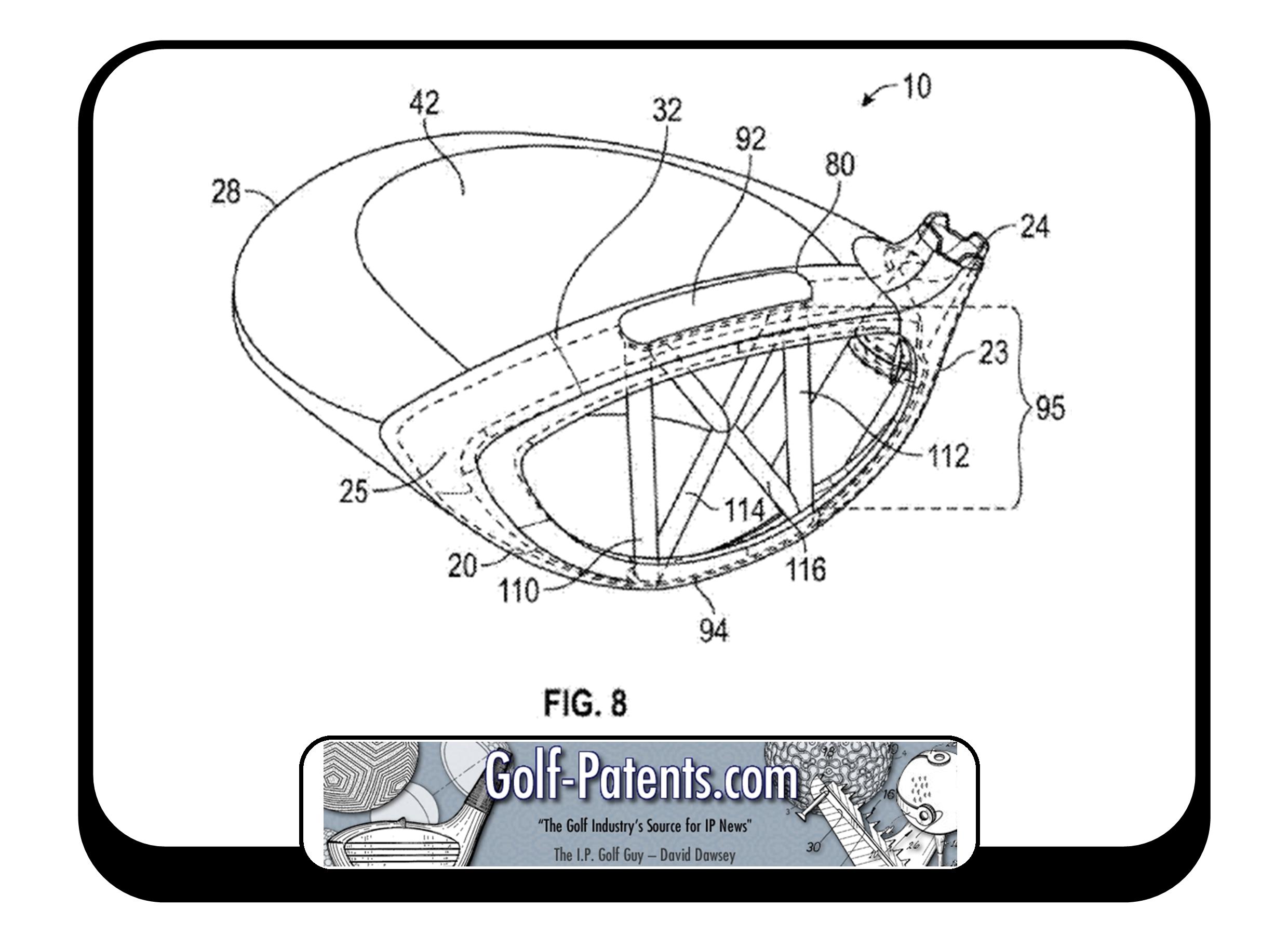
[0028] In the embodiment shown in FIG. 7, the middle portion 95 of the elongated cartridge 90 includes three piston assemblies 100, each with a rod 102 and a tube 104 portion to permit compression of the elongated cartridge 90 when the golf club head 10 impacts a golf ball. The rod 102 is capable of sliding into the tube 104 when the elongated cartridge 90 is placed in compression. In the embodiment shown in FIG. 8, the middle portion 95 of the elongated cartridge 90 includes a pair of vertical rods 110, 112 extending between the upper and lower portions 92, 94 and a pair of diagonal rods 114, 116 extending between the vertical rods 110, 112 and forming an “X” shape. This X-shaped structure provides additional support for the vertical rods 110, 112 and thus the striking face section 30. In the embodiment shown in FIG. 9, the middle portion 95 of the elongated cartridge 90 is a hollow rectangular box 120 composed of one or more lightweight, strong materials such as carbon composite, steel, aluminum alloy, or titanium alloy.
[0031] As shown in FIG. 4, in each of the embodiments disclosed herein, each stiffening member 50 or feature of the stiffening middle portion 95 of the elongated cartridge 90 is located less than 0.500 inch from the rear surface 36 of the striking face section 30, measured along a vertical plane 60 extending through the face center 34 perpendicular to the striking face section 30. No portion of any stiffening member 50 or middle portion 95 should be disposed outside of this 0.500 inch range. As shown in FIG. 5, the middle stiffening member 50b or center-most structure of the middle portion 95 preferably is disposed within 0.250 inch, toe-wards or heel-wards, of the face center 34 along a horizontal Y-axis 70 extending parallel to the striking face section 30. The other two stiffening members 50a, 50c, or the outer edges of the middle portion 95 of the elongated cartridge 90, preferably are each disposed within 1 inch, toe-wards and heel-wards, of the face center 34 along the Y-axis 70.
[0032] Locating the stiffening members 50 or middle portion 95 of the elongated cartridge 90 within the region of the golf club head 10 defined above and in FIGS. 4 and 5 has the greatest stress-reducing effect on the golf club head 10. If any of the stiffening members 50 are placed more than 0.500 inch away from the rear surface 36 of the striking face section 30 or outside of the 0.250/1 inch range, they will not have a noticeable effect on the stress placed on the striking face section 30 when the golf club head 10 is in use, and will use up discretionary mass without creating a significant performance benefit.
So there you have it, while not a lot of enlightening information, it is nonetheless a glimpse of what may be associated with those mysterious spy pics.
What do you think, is it EPIC?
Dave Dawsey – The Golf Patent Attorney
PS – follow me on Twitter (@GolfPatents) and sign-up HERE to receive posts via email.
PPS – If you like what we are doing, please considering helping us out and make your online gear purchases through our Amazon affiliate link. Every little purchase helps us keep the site up and running! Thanks.