
The Future of Golf Ball Technology?
Probably not, but a pretty cool invention by Nike Golf nonetheless (even if it screams… “much easier for a patent attorney to write than it will be to produce”).
The patent goes on to explain:
BACKGROUND
In the game of golf, players use a club to strike a golf ball towards a hole in the ground. Often the hole is surrounded by hazards, including water hazards such as ponds, lakes, and even the ocean. Golf balls that enter the water hazards typically sink because regulation golf balls are denser than water. Retrieving golf balls that have sunk into the water hazards is difficult, and golf balls left in the bodies of water may pose an environmental risk. It would be advantageous to provide a golf ball that can be easily retrieved from a water hazard.
SUMMARY
The golf ball of the present disclosure is designed to change mass after prolonged submersion in water. The change in mass allows the golf ball to float to the surface of the water hazard after being submerged. The loss of mass is typically achieved by providing pockets within the golf ball containing dense material. The dense material is held within the pockets by water soluble material. When the water soluble material is dissolved when the golf ball is submerged in water, the buoyancy of the golf ball changes from negative to positive, this allowing the golf ball to float to the surface.
.
.
.
.
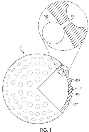
Conduit 105 has dimensions, such as a diameter or width. FIG. 2 shows conduit 105 having a diameter D. Conduit diameter D may be selected to control flow of materials moving between cavity 103 and the exterior of golf ball 101. For example, objects larger than conduit diameter D may not be able to enter or exit cavity 103. Thus, conduit diameter D may be selected to prevent objects larger than a predetermined size from entering or exiting cavity 103.As shown in FIG. 2, conduit 105 is a narrow passageway through cover 115. In other embodiments, conduit 105 may have other configurations. However, in those embodiments where conduit 105 is a narrow passageway, the size and dimensions of conduit 105 may be used to control the movement of material through conduit 105. For example, when any of the dimensions of the particles of the dense removable material are larger than the largest dimension of conduit 105, the geometry of conduit 105 blocks the movement of the dense removable material through conduit 105.
Conduit 105 may terminate or have a termination point at any location of the outermost surface of golf ball 101. The terms “terminate” and “termination point” used here refer to where the aperture or mouth of conduit 105 breaks through cover 115 and any coating or other layers to provide a path from cavity 103 to the environment surrounding golf ball 101. As shown, conduit 105 terminates within dimple 107. Positioning the termination point within dimple 107 may help to prevent unintentional opening of conduit 105, as the material blocking or plugging conduit 105 may be more brittle than the material of cover 115. Typically, the bottom of dimple 107 deforms less than the material of land 109 when golf ball 101 is struck by a golf club. Therefore, less strain may be placed on the material blocking or plugging conduit 105 if the termination point of conduit 105 is placed in the bottom of dimple 107. However, in other embodiments, the termination point may be in dimple 107, on land 109, or combinations of dimple 107 and land 109 locations, even for the same termination point.
Cavity 103 may contain one or more composites 121. Composites 121 may comprise particles of a first material 123 bound together by a water-soluble second material 125. FIG. 3 shows an embodiment of composite 121. Though shown as a cube, composite 121 may have any size or shape. Composite 121 may include a longest dimension, such as a leg length, a diameter, or the like. The longest dimension may be considered the longest composite dimension, where the longest composite dimension controls the ability of composite 121 to move within cavity 103, conduit 105, and/or through the conduit aperture or mouth.
First material particles 123 may by any suitable material having a density greater than water. For example, appropriate materials may include but are not limited to glass, sand, other ecologically friendly materials (e.g., materials having substantially no, minimal, or limited negative impact on the surrounding environment), other ecologically inert materials (e.g., materials having no ability to interact with the surrounding environment), and/or combinations of these materials. First material particles 123 may be of any shape or configuration. As shown in FIGS. 2-3, first material particles 123 are spherical pellets of material. However, in other embodiments, first material particles 123 may be pellets having any regular or irregular shape, such as cylindrical, spheroid, uneven, polygonal, powdered, and/or combinations of these shapes. First material particles 123 may have a diameter or width smaller than conduit diameter D.
First material particles 123 provide the bulk of the mass to composite 121. When composites 121 are placed in cavity 103, the mass of golf ball 101 may be increased, sometimes significantly, for example, if extremely dense materials as compared to water are used for first material particles 123. The mass of golf ball 101 may thus be varied by the addition and removal of first material particles from cavity 103. This variation in mass may be sufficient to alter the buoyancy of golf ball 101 from negative, so that golf ball 101 tends to sink, to positive, so that golf ball 101 tends to float. Another advantage to having a denser-than-water material positioned proximate cover 115 is to increase the moment of inertia of golf ball 101 by shifting mass toward cover 115.
Second material 125 may be any suitable water-soluble bonding material. Second material 125 may be a water-soluble epoxy, salts, starch-based binders, various polymers such as depart, and/or other types of water soluble materials. Second material 125 may bond together first material particles 123 into compos
ite 121. In addition to being water soluble, second material 125 may include particles which bubble or fizz when the particles react with water. For example, second material 125 may include particles of sodium bicarbonate and citric acid along with more robust water soluble materials. The sodium bicarbonate dissociates into sodium (Na+) and bicarbonate (HCO3-) ions in water. The bicarbonate reacts with hydrogen ions (H+) from the citric acid to form carbon dioxide and water. The carbon dioxide forms bubbles. This fizzing or bubbling action may assist in expelling first material 123 from cavity 103 when golf ball 101 is submerged in water.
.
.
.
.
The operation of the embodiment of golf ball 101 in use will now be explained using FIGS. 4-7. During play, golf ball 101 may be struck into a body of water 131. Body of water 131 contains water 133.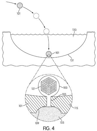
The initial density of golf ball 101 may be configured to be greater than water 133. In other words, golf ball 101 will be negatively buoyant in water. Therefore, when golf ball 101 enters body of water 131 golf ball 101 sinks to the bottom. FIG. 4 illustrates this effect.
FIG. 4 also illustrates the initial state of cavity 103. Cavity 103 may be filled with a plurality of composites 121 and air. Each composite 121 may have dimensions larger than conduit diameter D, which prevents composite 121 from moving through conduit 105. The inability of the removable materials in cavity 103 to travel through conduit 105 allows the mass and density of golf ball 101 to remain constant.
When golf ball 101 submerges in water 133, the cavity 103 may not initially fill with water 133. Cavity 103 may be configured to delay the entry of water. For example, conduit 105 may have a diameter D small enough that the exchange of air from within cavity 103 and water 133 from the exterior of golf ball 101 may take a predetermined length of time. For example, the process may take several hours, several days, or even several weeks. Alternately, as will be discussed in later embodiments, cavity 103 may include a plug preventing water 133 from entering the cavity 103.
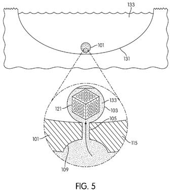
As golf ball 101 stays submerged in water 133 for a period of time, cavity 103 may begin filling with water 133. FIG. 5 illustrates this effect. Cavity 103 may be configured to allow water to fill cavity 103 after a predetermined period of time.
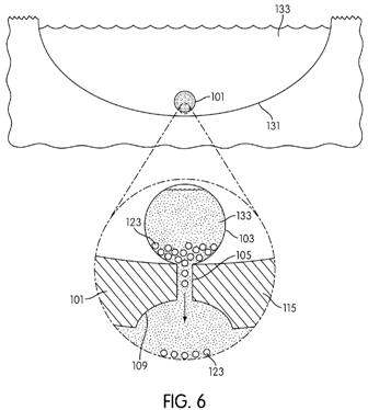
Once water 133 has filled cavity 103, the water 133 may begin to dissolve the water-soluble second material 125. As second material 125 dissolves, the structural integrity of composite 121 may fail. Over time, composite 121 may be completely dissolved, leaving only unbound first material particles 123. In some embodiments, portions of first material particles 123 are freed from composite 121 over time. This may act as a second time delay for allowing golf ball 101 to float, as the buoyancy of golf ball 101 will shift from negative through neutral to positive only when a predetermined number or amount of first material particles 123 are unbound and travel through conduit 105 to the environment surrounding golf ball 101. In the embodiment shown in FIG. 5, the environment comprises water 133.FIG. 6 shows cavity 103 after composite 121 has dissolved completely. First material particles 123 may float freely within cavity 103. First material particles 123 are smaller than the conduit diameter D. Thus, as shown in FIG. 6, first material particles may exit cavity 103 through conduit 105. As discussed above, this process does not require composite 121 to completely dissolve. A predetermined portion of composite 121 may dissolve to allow a sufficient amount of first material particles to flow out of golf ball 101 through conduit 105 to allow the buoyancy of golf ball 101 to shift from negative to positive.
.
.
.
.
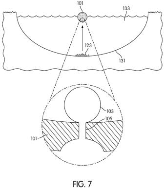
FIG. 7 shows the effect that the change in mass has on golf ball 101. When the density of golf ball 101 falls below the density of water 133, golf ball 101 may float to the surface of body of water 131. Golf ball 101 may be more easily retrieved from body of water 131 in this state.
Kudos for thinking green, now prove me wrong by actually bringing it to market!
David Dawsey – Keeping an Eye on Golf Ball Technology
PS – Click HERE to check out more interesting golf ball inventions.