
Test Your MOI Knowledge & Check Out Some Creative Acushnet Club Head Designs
In the past I have profiled some rather unusual, some may say unique, golf club designs by Callaway, Taylor Made, and Bridgestone; however I have never reported on any Acushnet patent applications disclosing club head designs that lean toward the unconventional. Today is a new day and an Acushnet patent application published yesterday that will make you think.
The patent application published as US Pub. No. 20090149276 titled “Metal Wood Club With Improved Moment of Inertia” and described the invention as:
A golf club head having at least two discrete weight members positioned on the sole to optimize moment of inertia is disclosed. A first weight member is located toward and substantially parallel with the face edge of the sole. A second member is located toward the back of the sole and substantially centered between the heel and toe edges of the sole. In one embodiment, a golf club head includes a sole comprising four sections and wherein a rib of material connects two of said sections. In another embodiment, a golf club head includes a cavity formed between the crown and sole and having an opening at the back of the club head. In yet another embodiment, a golf club head is tapered to form a waist and has a back that has a bowed-shape.
OK, that description does not do justice to the club head designs that you are about to see.
The application goes on to provide a nice bit of background on club head design:
[0002] The complexities of golf club design are known. The specifications for each component of the club (i.e., the club head, shaft, grip, and subcomponents thereof) directly impact the performance of the club. Thus, by varying the design specifications, a golf club can be tailored to have specific performance characteristics.
[0003] The design of club heads has long been studied. Among the more prominent considerations in club head design are loft, lie, face angle, horizontal face bulge, vertical face roll, center of gravity, rotational moment of inertia, material selection, and overall head weight. While this basic set of criteria is generally the focus of golf club designers, several other design aspects must also be addressed. The interior design of the club head may be tailored to achieve particular characteristics, such as the inclusion of a hosel or a shaft attachment means, perimeter weights on the club head, and fillers within the hollow club heads.
[0004] Golf club heads must also be strong to withstand the repeated impacts that occur during collisions between the golf club and the golf balls. The loading that occurs during this transient event can create a peak force of over 2,000 lbs. Thus, a major challenge is to design the club face and club body to resist permanent deformation or failure by material yield or fracture. Conventional hollow metal wood drivers made from titanium typically have a uniform face thickness exceeding 2.5 mm or 0.10 inch to ensure structural integrity of the club head.
[0005] Players generally seek a metal wood driver and golf ball combination that delivers maximum distance and landing accuracy. The distance a ball travels after impact is dictated by the magnitude and direction of the ball’s initial velocity and the ball’s rotational velocity or spin. Environmental conditions, including atmospheric pressure, humidity, temperature, and wind speed, further influence the ball’s flight. However, these environmental effects are beyond the control of the golf equipment designers. Golf ball landing accuracy is driven by a number of factors as well. Some of these factors are attributed to club head design, such as center of gravity and moment of inertia.
[0006] Concerned that improvements to golf equipment may render the game less challenging, the United States Golf Association (USGA), the governing body for the rules of golf in the United States, has specifications for the performance of golf equipment. These performance specifications dictate the size and weight of a conforming golf ball or a conforming golf club. USGA rules limit a number of parameters for drivers. For example, the volume of drivers has been limited to 460+-10 cubic centimeters. The length of the shaft, except for putter, has been capped at 48 inches. The driver clubs have to fit inside a 5-inch square and the height from the sole to the crown cannot exceed 2.8 inches. The USGA has further limited the coefficient of restitution of the impact between a driver and a golf ball to 0.830.
[0007] The USGA has also observed that the rotational moment of inertia of drivers, or the club’s resistance to twisting on off-center hits, has tripled from about 1990 to 2005, which coincides with the introduction of oversize drivers. Since drivers with higher rotational moment of inertia are more forgiving on off-center hits, the USGA was concerned that further increases in the club head’s inertia may reduce the challenge of the game, and instituted in 2006 a limit on the moment of inertia for drivers at 5900 g*cm^2+-100 g*cm^2 or 32.259 oz*in^2+-0.547 oz*in^2. The limit on the moment of inertia is to be measured around a vertical axis, the y-axis as used herein, through the center of gravity of the club head.
[0008] A number of patent references have disclosed driver clubs with high moment of inertia, such as U.S. Pat. Nos. 6,607,452 and 6,425,832. These driver clubs use a circular weight strip disposed around the perimeter of the club body away from the hitting face to obtain a moment of inertia from 2800 to 5000 g*cm^2 about the vertical axis. U.S. Pat. App. Pub. No. 2006/0148586 A1 discloses driver clubs with moment of inertia in the vertical direction from 3500 to 6000 g*cm^2. However, the ‘586 application limits the shape of the driver club to be substantially square when viewed from the top, which in turn limits the mass characteristics of the club head.
[0009] However, most oversize drivers on the market at this time have moments of inertia in the range of about 4,000 to 4,300 g*cm^2. Hence, there remains a need for more forgiving driver, hybrid and utility hollow golf club heads with optimized moments of inertia.
[0010] The present invention is directed to a golf club head having a substantially I-beam-shaped mass distribution. More preferably, the present invention is directed to a driver, hybrid or utility hollow golf club head having a mass distribution that substantially resembles an I-beam or pseudo-I-beam to optimize the moment of inertia of the club head around the y-axis.
[0011] The golf club head of the present invention includes two discrete weight members, one located on the sole toward the face and one located on the sole toward the back. Said sole weight members may have greater density or thickness than the surrounding sole material. Alternatively, said weight members may comprise weights disposed on the surface of the sole. By placing mass in two discrete locations on the sole located away from the vertical axis that runs through the center of gravity of the club head, the rotational inertia of the club head about that axis is increased relative to a configuration in which mass is evenly spread around the sole.
[0012] In accordance with this invention, the club head may have a multitude of different shapes, although in each embodiment, weight is concentrated in distinct areas locations on the sole–at least one weight member is located on the sole toward the face and at least one weight member is located on the sole toward the back. According to an aspect of this invention, the weight member on the sole and toward the face may be divided into two zones of mass, and likewise the weight member on the sole and toward the back may be divided into two zones of mass.
Now, here is a primer on MOI:
[0024] Rotational moment of inertia (“MOI” or “inertia”) in golf clubs is well known in the art, and is fully discussed in many references, including U.S. Pat. No. 4,420,156, which is incorporated herein by reference in its entirety. When the inertia is too low, the club head tends to rotate excessively from off-center hits. A golf club head having a higher moment of inertia will resist rotation due to an off-center impact between the club face and a golf ball, thereby mitigating the tendency for the ball to hook or slice and increasing flight distance and landing accuracy. The present invention is directed to a hollow body golf club head having discrete concentrations of weight or mass located away from the center of gravity or the geometric center of the club head to optimize the moment of inertia of the club head about the vertical axis running through the center of gravity, hereinafter called the y-axis. In particular, the present invention is directed to a hollow body driver, hybrid or utility golf club head having the above-described mass characteristics.
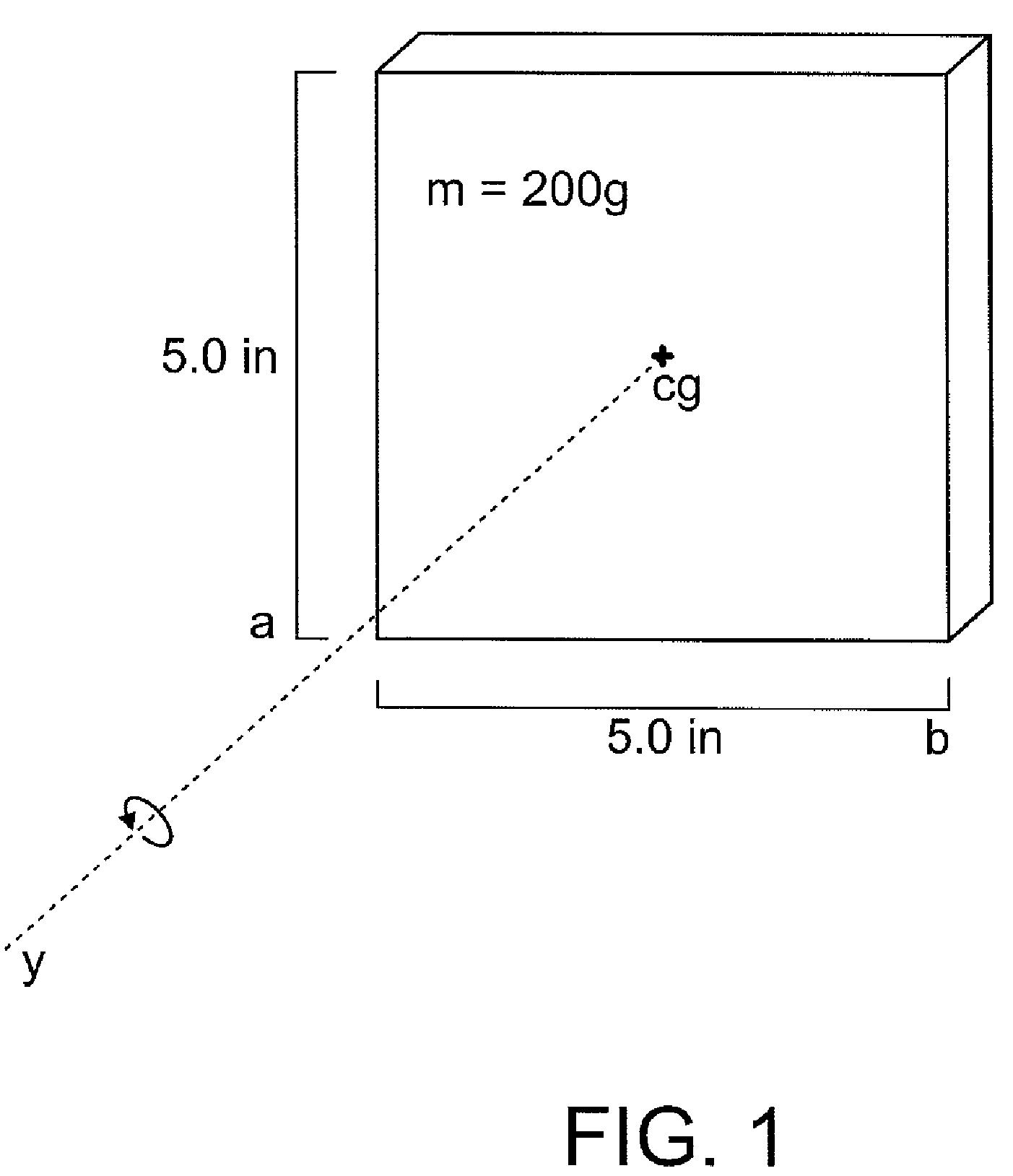
[0025] As is shown in FIG. 1, idealized club head 10 having an evenly-distributed mass m of 200 grams and sides a and b five inches in length, fitting into the USGA-prescribed five-inch box, will have a center of gravity at its center of mass. For objects rotating about a known axis of rotation, moment of inertia I can be calculated using the following equation:
I = m*r^2
where m is the mass of the object and r is the distance of that mass from the axis of rotation.
[0026] The moment of inertia of club head 10 about the y-axis can be described by this equation:
I = 1/12 *m* (a^2+b^2)
Using this equation, the moment of inertia of club head 10 is 833.33 g*in^2 or 5376.33 g*cm^2. Because the mass of club head 10 is evenly distributed, the individual point masses located near the y-axis do not contribute great amounts of inertia to the overall inertia of the club head, as their r values are small.
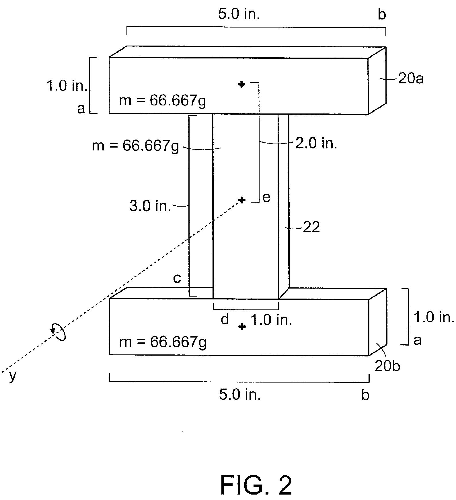
[0027] However, when the mass of the club head is concentrated in areas that are located farther away from the y-axis, their r values become bigger, resulting in increased moment of inertia. Like club head 10 of FIG. 1, idealized club head 12 of FIG. 2 has an overall length and width of 5 inches. The mass of club head 12 is 200.01 grams, nearly identical to that of club head 10, however club head 12 has an I-beam configuration. One weight member 22 having side c three inches in length, side d one inch in length, and a mass m of 66.67 grams is positioned between and perpendicular to two weight members 20a and 20b each having sides a one inch in length, side b five inches in length, and a mass m of 66.67 grams. The distance from the center of mass of weight member 20a or 20b to the center of mass of club head 12, which also serves as the point through which the y-axis runs, is called e, and is two inches in this case. The moment of inertia of the club head about the y-axis can be calculated by adding the moments of inertia of all three weight members, as is shown in the following equation:
I = 2 * [( 1/12*m* (a^2+b^2)) + m*e^2] + 1/12*m* (c^2+d^2)
This equation utilizes the Parallel Axis Theorem to determine the moments of inertia of weight members 20a and 20b. The moment of inertia of club head 12 is 877.78 g*in^2 or 5663.10 g*cm^2, resulting in a five percent increase in MOI over club head 10 of FIG. 1.
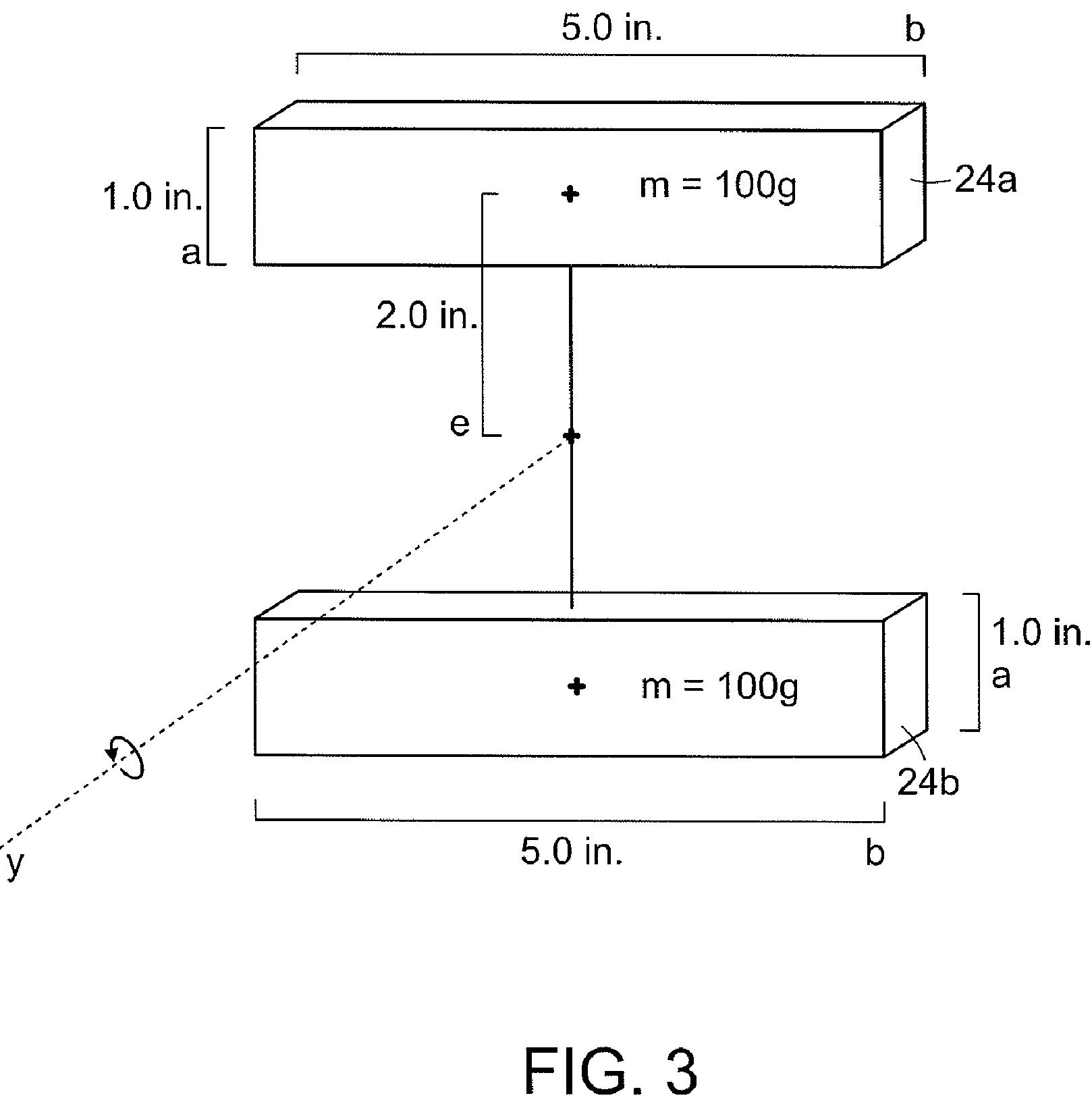
[0028] FIG. 3 shows another idealized club head 14, in which discrete weight members 24a and 24b are positioned around an axis of rotation. Because no weight member is located between weight members 24a and 24b, they are said to be arranged in a pseudo-I-beam configuration, as opposed to the I-beam configuration of FIG. 2. Club head 14 has an overall length and width of five inches and a total mass of 200 grams. Weight members 24a and 24b are five inches long and one inch wide, and each have a mass m of 100 grams. Weight members 24a and 24b are positioned three inches apart. As in FIG. 2, e is the distance from the center of mass of weight member 24a or 24b to the center of mass of club head 14 and the point through which the y-axis runs, and is two inches in this case. The moment of inertia of club head 14 can be described by this equation, which makes use of the parallel axis theorem:
I = 2* [( 1/12*m* (a^2+b^2)) + m*e^2]
In accordance with this equation, the MOI of club head 14 is 1233.33 g*in^2 or 7956.97 g*cm^2. This mass distribution offers a forty-eight percent increase in MOI over that of club head 10 of FIG. 1. When mass is allocated to areas located farther away from the axis of rotation, the r values of each point mass that makes up the entirety of the discrete weight member are large, resulting in much greater moment of inertia.
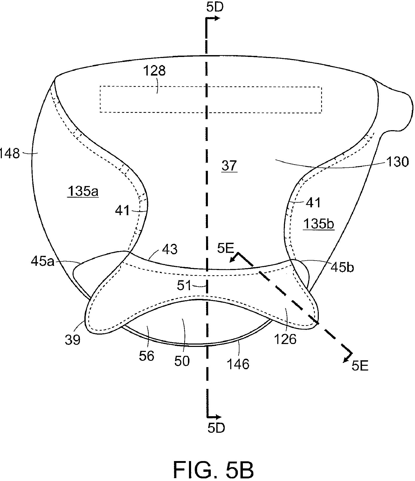
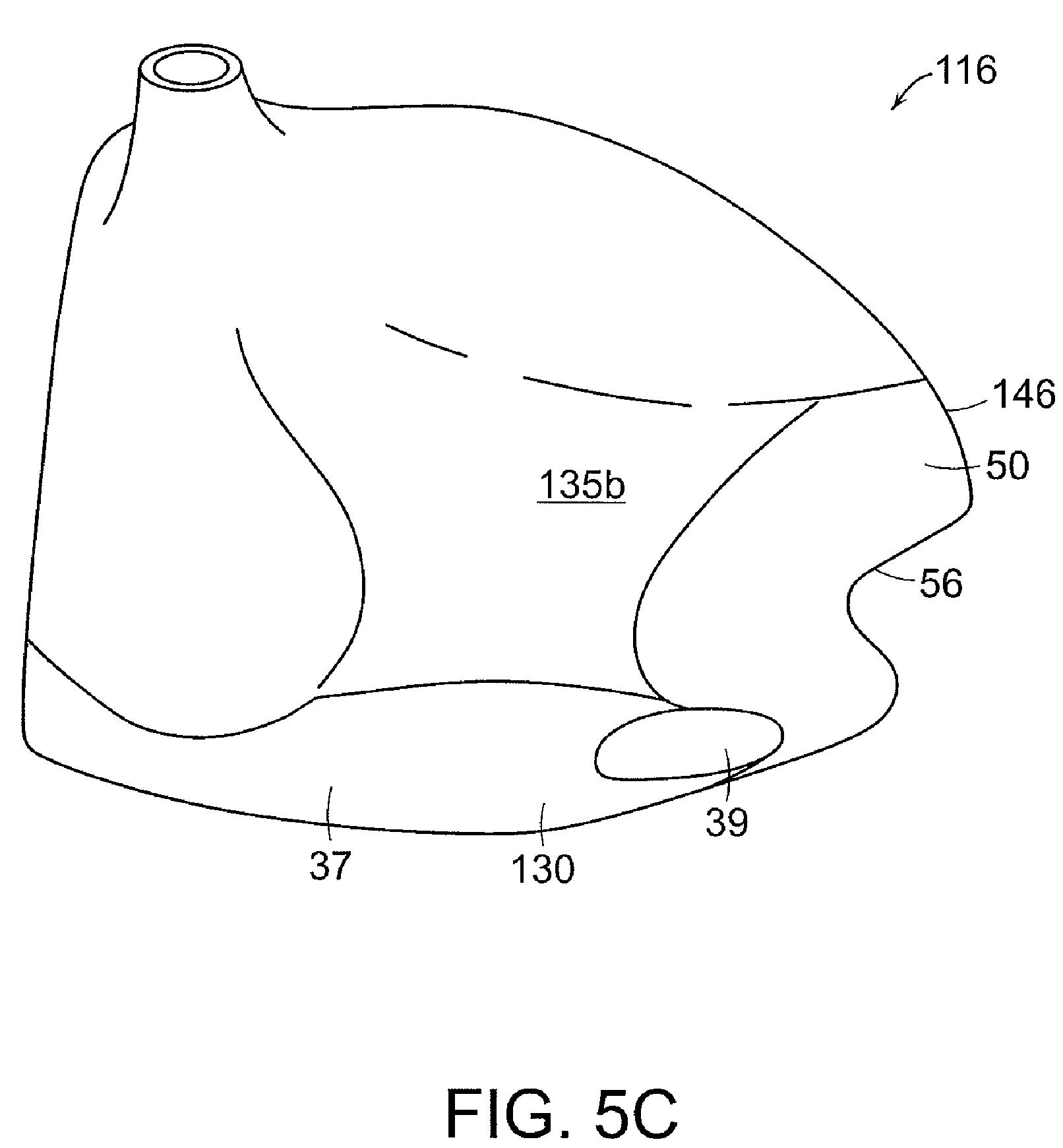
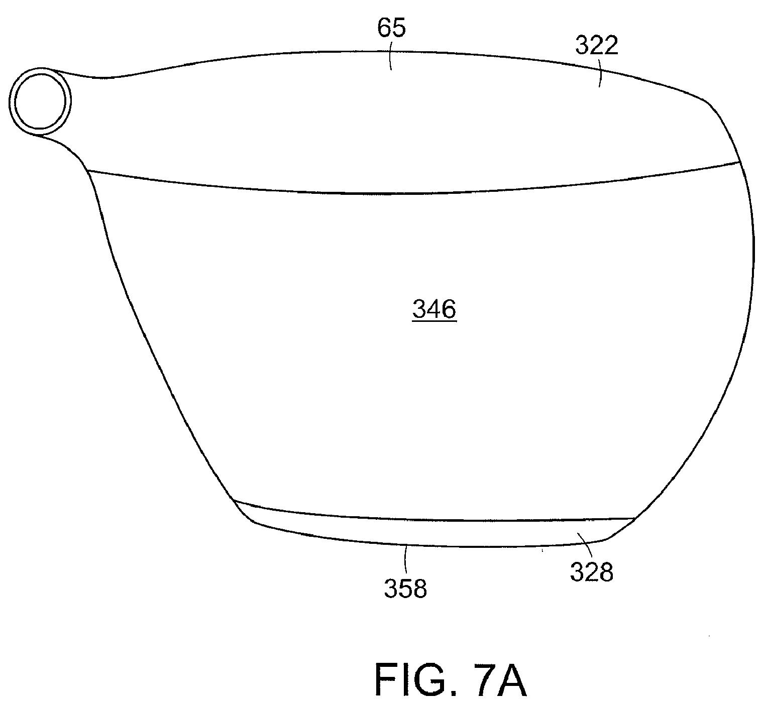
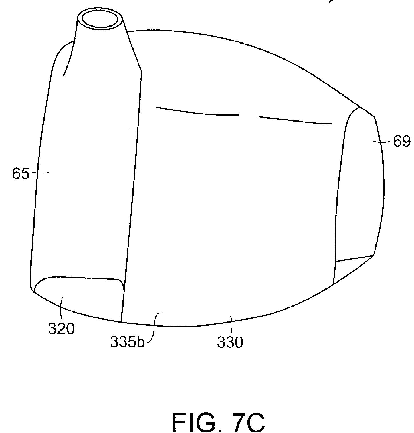
[0029] The golf club head of the present invention utilizes the I-beam and pseudo-I-beam mass distribution patterns discussed above to optimize moment of inertia about an axis of rotation that runs vertically through the center of gravity or geometric center of the club head. In one embodiment of the present invention, shown in FIGS. 4a-4c, golf club head 16 comprises a face, crown, sole, skirt, and hosel, wherein the sole further comprises two discrete weight members 26 and 28. In accordance with this embodiment, weight member 28 is located substantially parallel to and toward the face edge of sole 30 and is substantially centered between the toe and heel. Weight member 28 can have a rectangular shape. Preferably, weight member 28 is located between about 1.0 and 4.0 cm from the face edge of sole 30.
Well, that is all well and good (and probably only interesting to the engineers out there), but here comes the interesting stuff. Check out these possible club head designs:
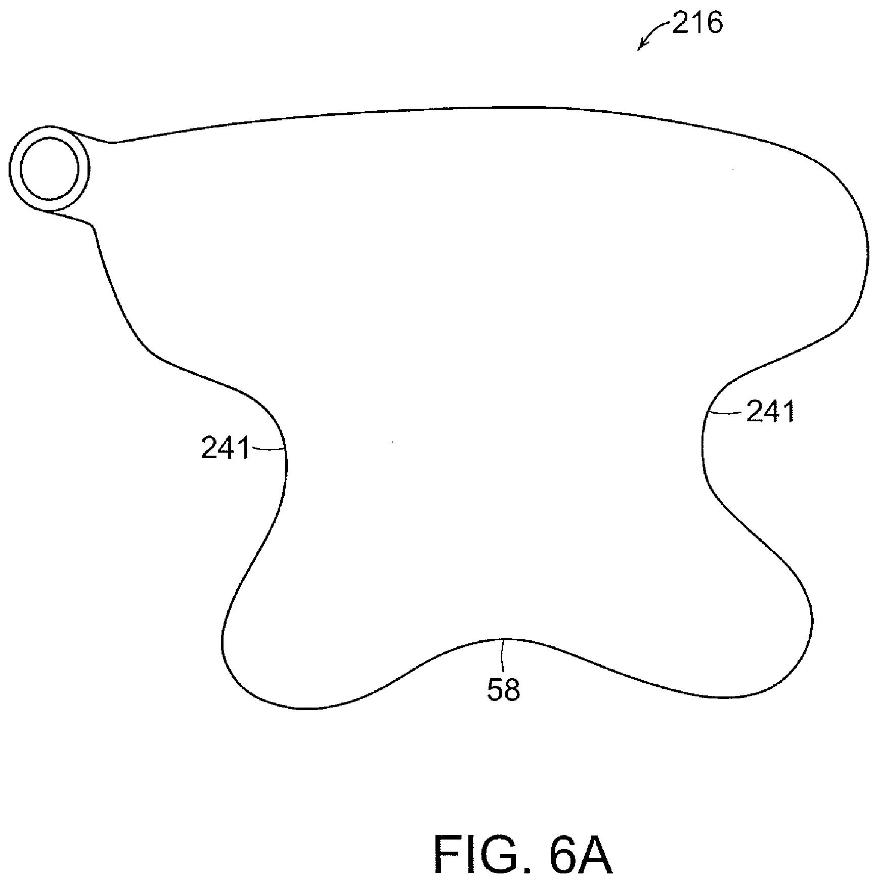
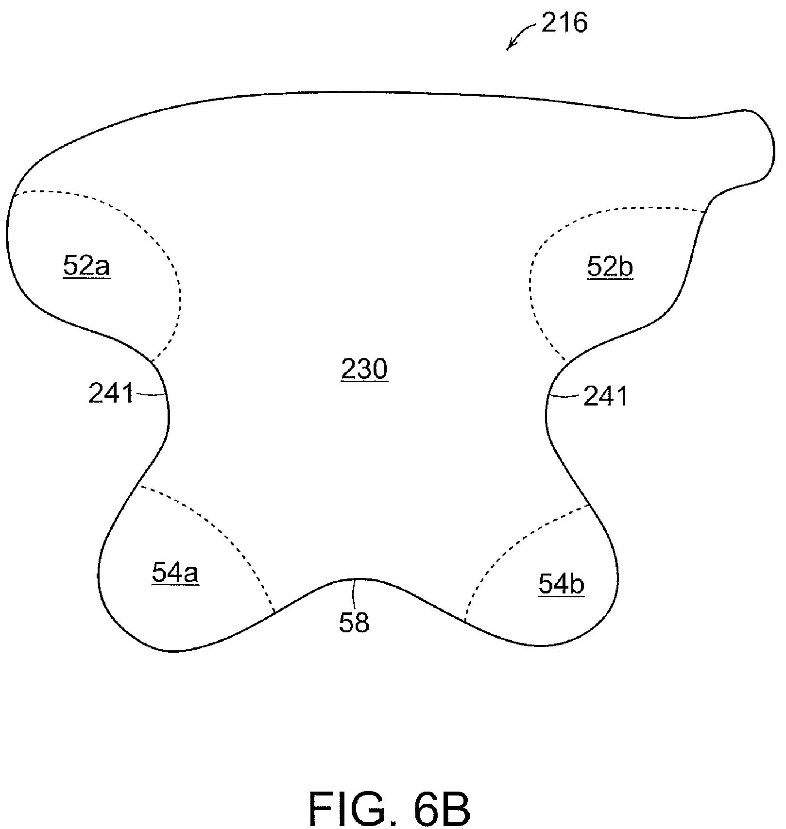
Fascinating, but will any of these designs make it into your pro shop?
Dave Dawsey – Monitoring Golf Driver Inventions
PS – click HERE to check out other golf driver intellectual property