
Talk About Alternative Energy! Why Not Generate Electrical Power From The Impact Of A Golf Club And Golf Ball?
Generally it is easy to dismiss golf ball locating systems as impractical or technically impossible. Recently I was about to dismiss yet another such patent application simply from the abstract and title, but upon scratching the surface I realized that there was an awful lot of technical disclosure in the application. This is a generally a sign that the application is directed to an actual invention rather than a nice idea supported only by smoke and mirrors. You be the judge.
The patent application that I refer to published as US Pub. No. 20090003136 titled “Impact Energy Powered Golf Ball Transmitter.”
Electrical power can be generated from impact based energy, such as from a golf ball being struck by a golf club. One or more piezo-electric devices, which are embedded in the core of the golf ball, are stressed by the impact and generate energy. Each piezo-electric device generates energy when stressed, which is then rectified and stored in a capacitor circuit. The stored energy in the capacitor circuit is used to power a transmitter to emit energy via an antenna, including all necessary electronics such as an oscillator, a modulator, and various control and logic circuits. The transmitted signals can be received by a hand held locator device. The described impact generated energy powers the transmitter a sufficiently long amount of time for the golfer to locate the golf ball. The impact based energy generation can also be used for other non-golf applications.
Sounds crazy, right? Well, don’t dismiss it just yet; the listed inventor has roughly 20 issued patents, with many directed to mobile communication systems for major companies. He seems to have the credentials. The application goes on to explain:
[0036] The present disclosure provides an elegant solution not found in prior implementations, where energy that is generated from a golfers swing is used to generate power for a transmitter circuit that is useful for locating the golf ball. The golfers swing generates a considerable amount of kinetic energy (e.g., on the order of 100 joules). The presently disclosed golf ball devices include a piezo-electric device. Upon impact with the golf ball device, the piezo-electric device converts a portion of the kinetic energy from the impact of the golfers swing into electrical energy.
[0037] Piezoelectricity is the ability of crystals and certain ceramic materials to generate a voltage in response to applied mechanical stress. The piezoelectric effect is reversible in that piezoelectric crystals can change shape by a small amount (about 1%) and then return to their original state while still retaining their crystalline properties. In addition to crystals of tourmaline, quartz, topaz, cane sugar, and Rochelle salt, many other materials exhibit the effect, including quartz analogue crystals like berlinite (AlPO.sub.4) and gallium orthophosphate (GaPO.sub.4), ceramics with perovskite or tungsten-bronze structures (BaTiO.sub.3, SrTiO.sub.3, Pb(ZrTi)O.sub.3, KNbO.sub.3, LiNbO.sub.3, LiTaO.sub.3, BiFeO.sub.3, Na.sub.xWO.sub.3, Ba.sub.2NaNb.sub.5O.sub.5, Pb2KNb5O15). Some plastic film materials such as Kynar film, a popular polyvinylidene fluoride film material, also have strong piezoelectric properties.
[0038] Direct piezoelectricity of some substances like quartz can generate potential differences of thousands of volts. In a piezoelectric crystal, positive and negative electrical charges in the crystal are separated, but symmetrically distributed, so that the crystal overall is electrically neutral. Each of these sites forms an electric dipole. Dipoles that are near one another tend to be aligned in regions called Weiss domains. When a mechanical stress is applied to the crystal, the symmetry of the positive and negative electrical charges is disturbed such that a voltage is generated across the material. For example, a 1 cm cube of quartz crystal can produce up to 12,500 volts when a 500 lb force (2 kN) is correctly applied to the crystal.
Example Implementations
[0039] FIG. 2 is a schematic diagram illustrating a golf ball device (200) arranged according to the present disclosure. The golf ball device (200) includes a radio frequency transmitter system (261), an antenna (262) and an impact based power generator system (263). The radio frequency transmitter system (261) includes a UHF transmitter (271), a code generator (272) and a resonator (273). The impact based power generator system (263) includes a piezo-electric device (281), a rectifier circuit (282), a capacitor circuit (283), and an optional resistor circuit (284).
[0040] The UHF transmitter (271) is a radio frequency (RF) transmitter that is capable of transmitting modulated signals via antenna 262 in a frequency band that is matched by the receiver in the locator device (see FIG. 1 discussion above). UHF or ultra-high frequency band transmissions are typically in the range from 300 MHz to 3 GHz. The resonator (273) is arranged to provide an oscillation signal that is used by the UHF transmitter (271). The code generator (272) can be arranged to cooperate with the resonator (273) and/or the UHF transmitter (271) to encode signals for transmission.
[0041] The code generator (272) can be any appropriate means that assigns a code to the golf ball device for identification purposes. The code can be uniquely assigned to each golf ball device (200), uniquely assigned to a sleeve of golf ball devices (i.e. a package of three golf balls are commonly sold in a single package referred to as a sleeve), or otherwise assigned to golf ball devices as may be desired. The code generator (272) can be implemented, for example, as a binary code that is set by a series of fuse links (or anti-fuse links) that are programmed during the manufacturing process, as an RFID tag device that is programmed by an RFID encoded radio frequency transmission, either during or after manufacturing the golf ball device, or by any other reasonable means to assign a code to the golf ball device (200). A code reader (e.g., 290) such as an RFID reader device with a corresponding antenna (291) can optionally be arranged to read the code from the golf ball device (200) via an RFID coded radio frequency transmission (e.g., 292). Example golf ball devices may be assigned codes as a linear or remapped count, making as above each ball or sleeve of balls unique. The number of required unique codes can be reduced when balls that are shipped to various regions are given codes that are distributed across the regions such that each region might have only a single occurrence of a code conflict. The number of regions assigned may be any designation such as country, state, continent or any other reasonable designation. The codes can optionally be assigned to the RFID tag via an RFID coded radio frequency transmission signal.
[0042] An example resonator (273) can be any appropriate high-frequency oscillator such as an electro-magnetic resonator, a cavity-based resonator, a waveguide based resonator, a coil based resonator, a ceramic based resonator, a piezo electric quartz crystal resonator, a silicon based Micro Electro Mechanical Systems (MEMS) resonator, a dielectric based resonator, or any other equivalent circuit that operates as a resonator. The code generator (272) is arranged to provide a code that can be used as a part of a signal transmission to identify the golf ball to distinguish it from other golf balls. The signal transmission can be encoded, encrypted or scrambled so that reception is unintelligible without using the same code (e.g., a spread spectrum communication or a narrowband communication).
[0043] The piezo-electric device (281) in arranged to generate electrical energy in response to mechanica
l stress from the impact between the golf ball device (200) and a surface. The impact can be the result of hitting the golf ball device (281) with the surface of a golf club (not shown), or as a result of the golf ball device (281) striking an environmental surface such as the ground, a tree, etc. At least a portion of the kinetic energy from the impact with the golf ball device (200) causes a mechanical stress on the piezo-electric device (281), resulting in the generation of high-voltage spikes (e.g., in excess of 1000 V) that are coupled to the rectifier circuit (282). The rectifier circuit (282) is arranged to block reverse current flow and permit forward conduction to charge the capacitor circuit (283) using charges generated by the high-voltage spikes from the piezo-electric device (281). The energy stored in the capacitor circuit (283) serves as a power supply (V+, V-) for the radio frequency transmitter system (261) in the golf ball device (200). The rectifier circuit (282) can be any appropriate device or arrangement of devices including but not limited to a half wave rectifier, a full wave rectifier, or a bridge rectifier. The optional resistor circuit (284) can have a very high effective resistance value (e.g., 1 M-ohm) that is coupled in parallel with the piezo-electric device (284) to permit the charges in the piezo-electric device to return to their de-stressed/de-strained (hereinafter simply de-stressed) state after the impact and recoil from the mechanical stresses have subsided.[0044] The piezo-electric device (281) can be any appropriate device that generates energy as a result of mechanical stress, such as a crystal material or a ceramic material. Mechanical stress on the golf ball device (200) acts as an impulse generator that disturbs the natural state of the piezo-electric device (281). A high-voltage spike (e.g., in excess of 1000 V) can be generated from the mechanical stress of impact. As the piezo-electric device (281) rebounds from the mechanical stress, a series of progressively decreasing amplitude positive and negative voltage spikes occur. The piezo-electric device (281) can be modeled as a resonant circuit such as an LC tank circuit, where the impact energy causes the resonant circuit to oscillate at a natural frequency (e.g., a crystals naturally occurring resonant frequency) for the piezo-electric device (281). The piezo-electric device (281) will eventually return to its resting state, where no oscillations occur.
[0045] As described above, the voltage spikes that are generated by the piezo-electric device can be considerable. These voltages spikes may be problematic for other circuits such as the radio frequency transmitter system (261). In this instance, another circuit can be interposed between the radio frequency transmitter system (261) and the impact based power generator system (263) such as by a voltage converter or limiter circuit (e.g., a DC-DC converter, a regulator, a peak limiter, etc.) so that inappropriate voltages are not coupled to the radio frequency transmitter system (261).
[0046] The efficiency of conversion from mechanical stress to electrical energy in a piezo device is not uniform and can be dependent upon the directional axis where the mechanical stress is applied. Additional piezo devices can be utilized in a variety of physical locations and orientations in the golf ball device to increase the energy efficiency as will be described below.
[0047] FIG. 3 is another schematic diagram illustrating another golf ball device (300) arranged according to the present disclosure. Similar to FIG. 2, the golf ball device (300) of FIG. 3 illustrates an impact based power generator system including a piezo-electric device (310), a rectifier circuit (320), and a capacitor circuit (330) that is arranged to serve as a power supply (V+, V-) for the radio frequency transmitter system (e.g., see FIG. 2) in the golf ball device (300).
[0048] For the example illustrated in FIG. 3, the piezo-electric device from FIG. 2 is replaced by three separate piezo-electric devices (311, 312 and 313). Each of the piezo-electric devices (311, 312 and 313) is coupled to the rectifier circuit (320). The rectifier circuit (320) is arranged as a three-phase rectifier circuit, where each piezo-electric device (311, 312 and 313) is associated with a different phase of the rectifier circuit (320). The rectifier circuit (320) can be arranged as any appropriate device that can rectify and combine the energy from the three piezo-electric devices at the capacitor circuit (330). In one example, each piezo-electric device (311, 312 and 313) has a separate rectifier circuit that shares a common output to the capacitor circuit. Separate resistor circuits (e.g., 284 of FIG. 2) can be placed in parallel with each piezo-electric device (284) to permit the charges in the piezo-electric devices (311, 312 and 313) to return to their de-stressed state after the impact and recoil from the mechanical stresses have subsided.
[0049] Also shown in FIG. 3, the piezo-electric devices (311, 312 and 313) are each in a different physical location (P1, P2 and P3) and orientation for energy conversion along an axis relative to the center (PC) of the golf ball device (300). In one example, piezo-electric device 311 is oriented for energy conversion along the y-axis at location P1, while piezo-electric device 312 is oriented for energy conversion along the x-axis at location P2, and piezo-electric device 313 is oriented for energy conversion along the z-axis at location P3. Each piezo-electric device (311, 312 and 313) is thus oriented such that maximum conversion of kinetic energy to electrical energy is achieved when the golf ball device (300) is impacted along the axis of the golf ball device (300) most aligned with the corresponding piezo-electric device. Although three devices are shown in the present example, any number of piezo-electric devices can be used to provide sufficient energy to power the various circuits. Moreover, the rectifier circuit can be represented as a multi-phase rectifier, where each phase is associated with a separate one of the piezo-electric devices.
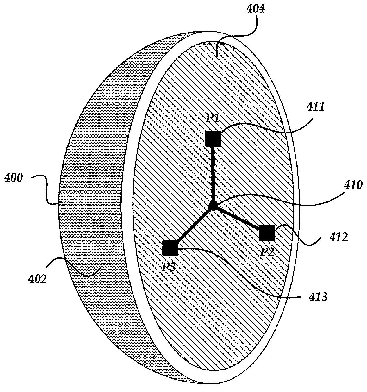
[0050] FIG. 4 is a cross-sectional view of a golf ball device (400) arranged according to the present disclosure. As shown in FIG. 4, the golf ball device (400) has an outer covering material (402), and an inner core material (404). Electronic circuits (410) are placed at the center of the inner core material (404) of the golf ball device (400) such as in the form of a system-on-chip (SOC) or integrated circuit (IC). Three piezo-electric devices (411-413) are couple to the electronic circuits (410), and oriented along separate axis (e.g., x, y, z) relative to the center of the inner core material (404). As described previously, the orientation and placement of each crystal at its relative position (P1, P2, and P3) is such that the maximum conversion of kinetic energy (e.g., a portion of the kinetic energy generated from impact between the golf ball device and a surface) to electrical energy is achieved.
The application also provides a nice synopsis of prior golf ball locating systems, which I have reproduced below.
BACKGROUND
[0002] A familiar problem for golfers is finding their golf ball once struck. A typical golf swing can result in hitting the golf ball over distances between several feet and several hundreds of yards. Ideally, the golfer can visually track the location of the ball once struck and thus easily find the golf ball. However, any number of a variety of environmental conditions may make it difficult to find the location of the golf ball. For example, the golfer may be playing in rain or fog conditions that make it very difficult to find the ball. Even on a bright sunlit day, the golfer may simply lose the ability to track the ball because of sun glare. Moreover, the golf ball may land in an environment (e.g., a wooded region, long grass, brush, bushes, etc.) that occludes a view to the ball. Beyond the embarrassment of losing the golf ball and a
ny imposed penalties in the game itself, golf players suffer a loss of time and broken concentration from trying to locate the golf ball.[0003] Various efforts have been proposed to facilitate locating golf balls. For example, GB1172449 teaches placing radioactive material inside a golf ball, and using a handheld Geiger counter to locate the ball. Since the amount of radioactive material that can be placed in the golf ball is limited due to human health and safety considerations, the radioactive detection method has a very limited detection range.
[0004] U.S. Pat. No. 5,132,622 to Valentino describes a golf ball with a metal center, where the golf ball can be found by scanning a metal detector over an area. The metal detector method also has limited range and is susceptible to false positive readings from extraneous metal materials located in the vicinity of the golf ball.
[0005] U.S. Pat. No. 7,140,972 to Redwine et al. describes a golf ball with an outer translucent later and an inner core that includes a luminescent liquid such as Cyalume, which can be activated by the impact of the golf club. Once activated, the golf ball may be more visible in low-light conditions due to the luminescent glow from the chemicals. However, in bright light conditions the luminescence is of no benefit.
[0006] U.S. Pat. No. 6,803,575 to McLaughlin describes treating an ordinary golf ball with an emulsion that deposits a hologram in the dimples. When illuminated by a laser beam at the proper pre-selected wavelength, the golf ball will reflects the laser beam. A hand held analyzer illuminates and detects the golf ball based on the reflected light at the specified wavelength. The hand held unit must be carefully aimed or detection is not possible.
[0007] U.S. Pat. No. 3,782,730 to Horchler describes a magnetically actuated switch, a radio oscillator circuit, and a battery located at the core of the golf ball. The radio oscillator is tuned on and off by the magnetically actuated switch. The radio signal from the radio oscillator can be monitored by the player to locate the golf ball whenever it is temporarily lost.
[0008] In U.S. Pat. No. 5,423,549 to Englmeier, a golf ball is describes that includes a rechargeable battery system and a transmitter that transmits electromagnetic signals. An external voltage source is used to recharge the battery through a wireless transmission. A mobile signal receiving unit is used to receive the transmitted signals from the golf ball to assist the golf player in locating the golf ball.
[0009] U.S. Pat. No. 5,112,055 to Barnhill describes a golf ball with a battery powered emitter that is activated by a switch when the golfer strikes the ball during a golf swing. Once active, the emitter provides an audible sound so that the golfer can locate the golf ball.
[0010] U.S. Pat. No. 5,626,531 to Little describes a transducer tag that is located within the golf ball, where the transducer tag includes a tuned capacitance that is activated by radiated energy from an external source. A detectable electronic signal is emitted from the golf ball when exposed to an electronic field at the proper frequency with sufficient energy to activate the transducer tag.
[0011] U.S. Pat. No. 5,662,534 to Kroll et al. describes a radio frequency reflector that is embedded in the golf ball. A monitor transmits a series of pulsed radio frequency beams to the golf ball, and analyzes the reflected radio waves.
[0012] U.S. Pat. No. 7,059,974 to Golliffe et al. describes a golf ball with a coded chip such as an RFID tag embedded in a resilient member. The resilient member is arranged to dampen shock to the coded chip, and can also prevent overheating of the coded chip during the manufacturing process.
[0013] U.S. Pat. No. 7,207,902 to Hamlin describes a golf ball with a passive transmitter and a pressure sensor, both located in a core region of the ball. The pressure sensor is used to determine golf course conditions surrounding the golf ball such as mud, dirt, water, sand, etc. A hand held unit is used to transmit energy at a selected frequency that can be received by the passive transmitter in the golf ball, which then transmits a response for reception by the hand held unit. Upon reception of the response, the hand held unit can determine distance to the golf ball and process the environmental conditions around the golf ball.
[0014] U.S. Pat. No. 7,095,312 to Carter describes a golf ball with a rechargeable power source, a GPS receiver, a GPS antenna, a motion sensor, a detector, a microprocessor, an RF transmitter and an RF antenna, all located within a core region of the golf ball. Prior to use, the rechargeable power source is charged and the GPS receiver attains a fix on a position from a GPS satellite. When the golf ball is placed in an area of use such as on a tee or mat in the tee box, the microprocessor is signaled by the detector to begin receiving and/or transmitting via either the GPS receiver/antenna or the RF transmitter/antenna. Additional positioning information is captured and recorded by the microprocessor while the golf ball is in flight. The motion sensor works with the microprocessor to detect when the golf ball has reached a resting position so that the collected positioning data can be transmitted via the RF transmitter/antenna. The collected data can be analyzed to evaluate flight path attributes such as traveled distance, speed, direction, loft, and trajectory.
[0015] While each of the above described golf ball devices may be suitable for the purposes for which they were designed, they may not be suitable in many other applications. The present disclosure contemplates each of the above described golf ball locators and identifies shortcomings in arriving at a novel solution.
Pretty cool idea that I would love to see make it to market, but I would have to see it work to believe it.
Dave Dawsey – Tracking Golf Ball Inventions and Patents
PS – click here, here, and here to check out other golf ball tracking inventions