
PING’s New Golf Tee Designed to Minimize a Tee’s Effect on Flight Trajectory and Spin
Would you ever think one of the big golf club OEM’s would get into the golf tee market? Not me, but that is just what Karsten seems to be considering. Yesterday Karsten had an interesting patent application publish as US Pub. No. 20090181806 titled “Golf Tee and Methods to Manufacture Golf Tees.” The application explains:
[0002] When hitting a golf ball with a golf club off a golf tee, resistance from the golf tee can have a measurable effect on, for example, a spin rate and/or a launch angle imparted by the golf club to the golf ball. In some cases, this may increase the spin rate of the golf ball at it leaves the golf tee, and can cause a flight trajectory of the golf ball to be higher than desired, and/or a travel distance of the golf ball to be shorter than desired. Minimizing resistance from the golf tee to the golf ball can be beneficial to achieving the intended flight trajectory and/or travel distance for the golf ball.
Check out these designs.
The application goes on to explain:
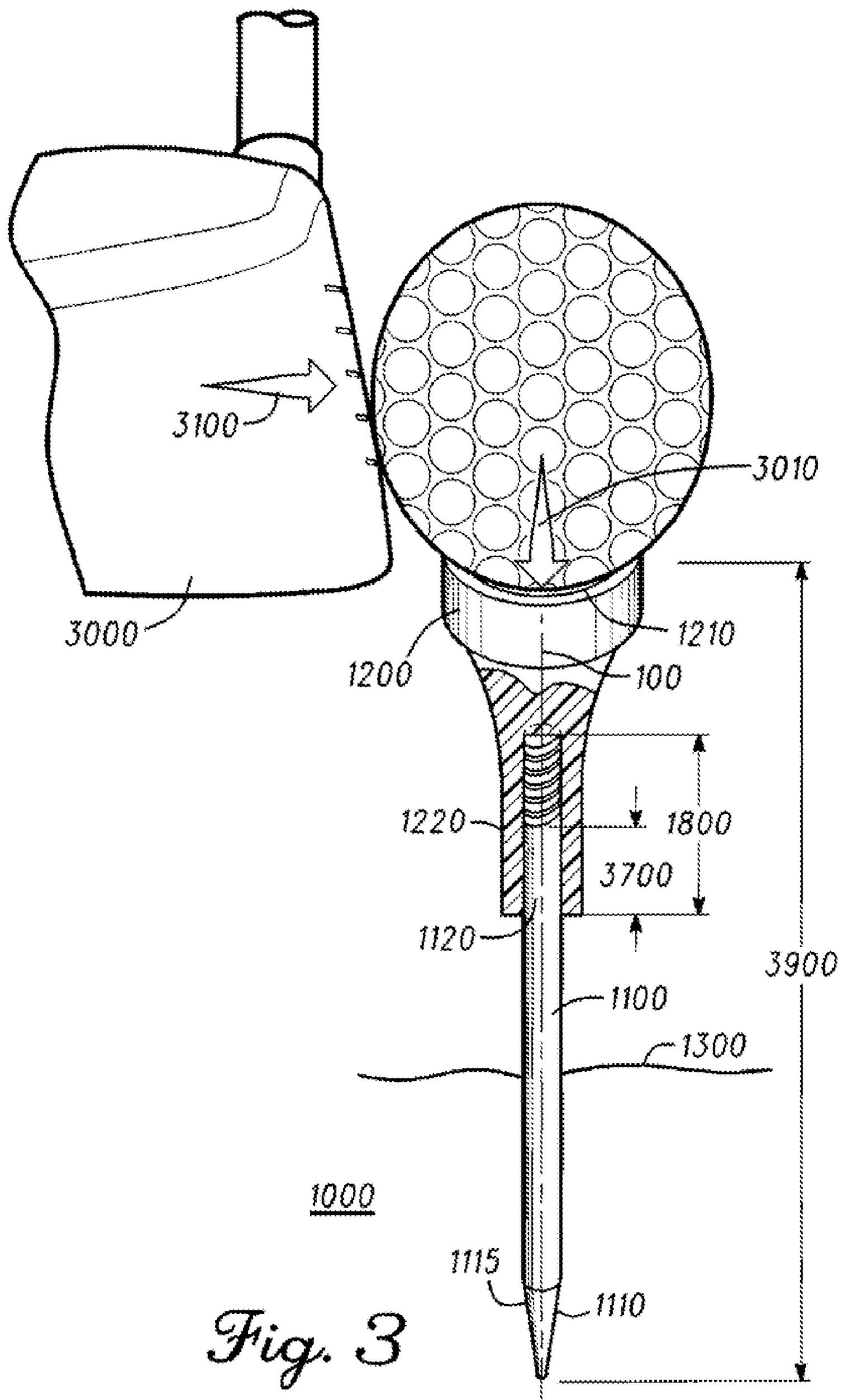
[0037] Referring now to the figures, FIG. 1 illustrates a partial cross-sectional view of golf tee 1000 in a relaxed configuration. FIG. 2 illustrates a partial cross-sectional view of golf tee 1000 in a semi-compressed configuration while supporting a golf ball. FIG. 3 illustrates a partial cross-sectional view of golf tee 1000 in a more compressed configuration as the golf ball is struck by a golf club. The relaxed configuration can be referred to as an extended configuration, and the semi-compressed or compressed configuration can be referred to as a semi-retracted or retracted configuration, respectively.
[0038] As illustrated in the examples of FIGS. 1-3, golf tee 1000 may support a golf ball over a golf-playing surface. An individual may use a golf club to hit the golf ball off of golf tee 1000 to minimize interference from the golf-playing surface. In the present example, the golf ball is illustrated as golf ball 2000 in FIGS. 2-3, while the golf club is illustrated as golf club 3000 in FIG. 3. Golf tee 1000 provides additional benefits not found in traditional golf tees, as will be described below.
[0039] In the present example of FIGS. 1-3, golf tee 1000 is presented as already positioned over golf-playing surface 1300. Golf-playing surface 1300 can be any kind of surface over which an individual might want to position golf ball 2000. In one example, golf-playing surface 1300 comprises the surface of a tee box on a golf course. In a different example, golf-playing surface 1300 can comprise other surfaces of a golf course, such as sand traps, fairways, rough areas, and even surfaces off a golf course such as a driving range. Although golf-playing surface 1300 is presented as substantially flat in FIGS. 1-3, it is not restricted to being flat, but can be angled or sloped, as long as it can provide the necessary support for golf tee 1000 to hold golf ball 2000.
[0040] Golf tee 1000, as shown in FIGS. 1-3, comprises portion 1100 and portion 1200. In some embodiments, portion 1100 can comprise a base portion to support golf tee 1000, while portion 1200 can comprise a support portion to support a golf ball. Portion 1100 comprises pairing section 1120, which is complementary to pairing section 1220 on portion 1200. In some embodiments, pairing sections 1120 and 1220 can be referred to as coupling sections.
[0041] The complementary nature of pairing sections 1120 and 1220 allows them to securely couple together, and thereby couple portion 1100 with portion 1200, such that portion 1100 can support portion 1200 when golf tee 1000 is in use. As a result of the coupling between portion 1100 and portion 1200, as in the present example, portion 1100 and portion 1200, and more specifically pairing sections 1120 and 1220, may overlap by an overlap distance 1700 with respect to each other.
[0042] In one embodiment, portion 1100 and/or portion 1200 can comprise a metallic material, a wooden material, a nylon material, and/or a polypropylene material. Portions 1100 and 1200 can comprise same materials or different materials. The apparatus, methods, and articles of manufacture described herein are not limited in this regard.
[0043] Portion 1100 of golf tee 1000 comprises base section 1110 that can serve to support golf tee 1000 in a position over golf-playing surface 1300. Base section 1110 is located at an end of portion 1100 opposite from pairing section 1120. In the present embodiment, base section 1110 includes pointed spike 1115 to insert into golf-playing surface 1300. Pointed spike 1115 can be dull or sharp. Friction exerted around pointed spike 1115 by golf-playing surface 1300 keeps base section 1110, and the rest of golf tee 1000, in position over golf-playing surface 1300. Although in the present embodiment base section 1110 is illustrated to include pointed spike 1115, base section 1110 could be implemented otherwise without deviating from the inventive concepts described herein. For example, in one embodiment, base section 1110 could be implemented via a flat surface that rests on top of golf-playing surface 1300. In a different embodiment, base section 1110 could be part of, or permanently attached to, golf-playing surface 1300.
[0044] Portion 1200 of golf tee 1000 comprises support section 1210 to support golf ball 2000 over golf-playing surface 1300. Support, section 1210 is located at an end of portion 1200 opposite from pairing section 1220. In the present embodiment, support section 1210 is represented as a cup curvature on top of portion 1200. The cup curvature can be complementary to a spherical surface section of golf ball 2000. As illustrated in FIG. 2, the cup curvature of portion 1200 can couple to the spherical surface section of golf ball 2000, allowing support section 1210 to retain golf ball 2000 in place over golf-playing surface 1300 when golf ball 2000 is positioned over portion 1200 of golf tee 1000. Although in the present embodiment support section 1210 is illustrated as a cup, support section 1210 could be implemented otherwise without deviating from the inventive concepts described herein. For example, in one embodiment, support section 1210 could be implemented via a prong mechanism, wherein prongs are configured to contact different points on the spherical surface section of golf ball 2000 to retain golf ball 2000 in position over portion 1200.
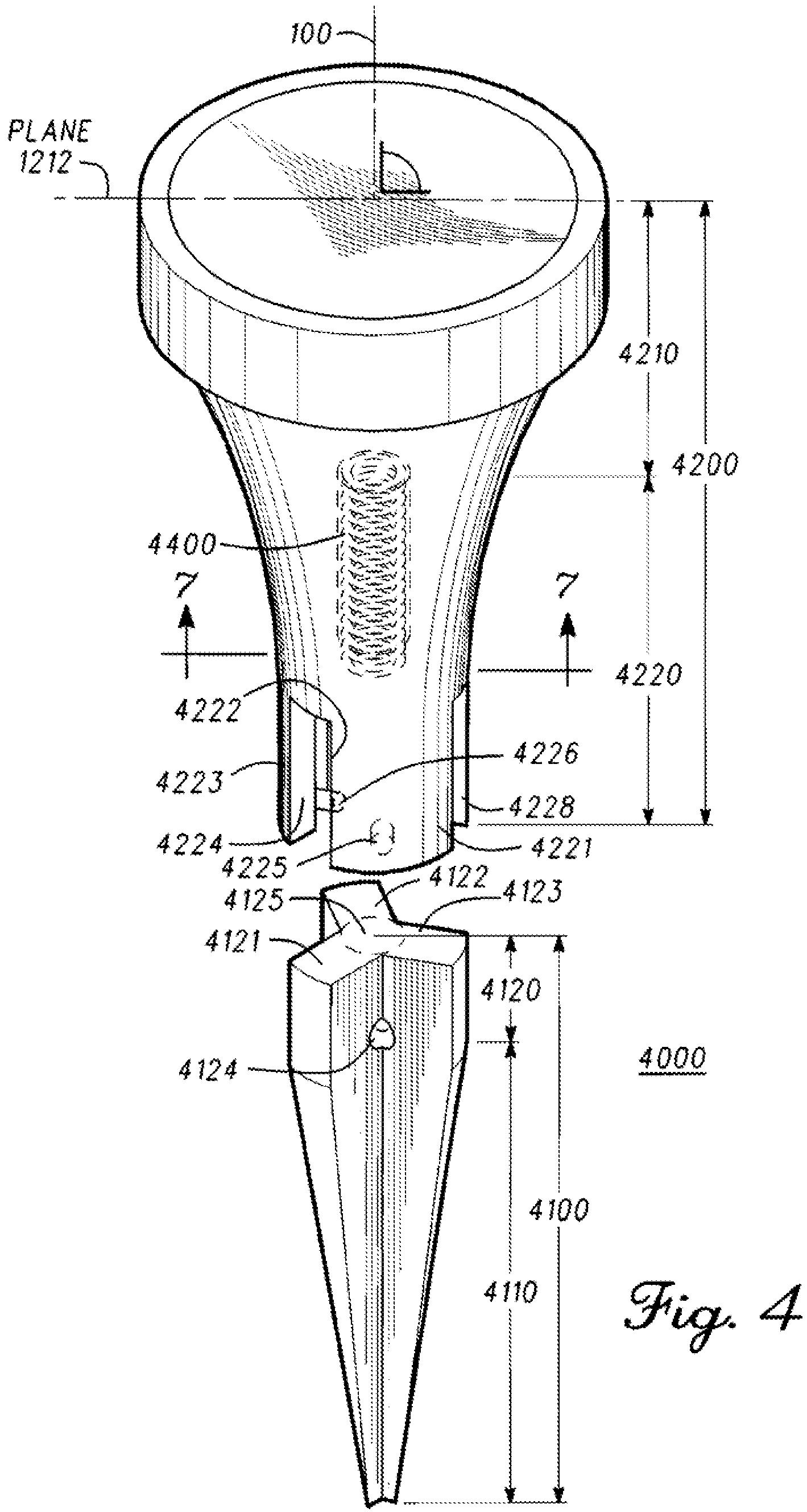
[0045] In the present embodiment, as illustrated in FIG. 1, an axis 100 crosses through golf tee 1000 parallel to longest dimension 1500 of golf tee 1000. In addition, perimeter 1211 of support section 1210 defines plane 1212 substantially perpendicular to axis 100. Longest dimension 1500 comprises the distance between an end of portion 1200, at support section 1210, to an end of portion 1100, at base section 1110. Axis 100, collinear within center section 1600 of golf tee 1000, crosses through portion 1200 and continues through portion 1100, from end to end of golf tee 1000. As an example, FIG. 1 shows axis 100 passing through golf tee 1000 and being substantially perpendicular to golf-playing surface 1300 while golf-playing surface 1300 supports golf tee 1000. The example of FIG. 1 also shows plane 1212 being substantially parallel to golf-playing surface 1300.
[0046] In the present example, section 1220 of portion 1200 also comprises displacement mechanism 1230 defining displacement distance 1800. FIGS. 1-3 represent displacement mechanism 1230 as chamber 1231. Physical dimensions of displacement mechanism 1230 at section 1220 are complementary to section 1120, permitting portion 1100 to couple with portion 1200. Once coupled, portion 1200 can move relative to portion
1100, along axis 100, as displacement mechanism 1230 displaces over section 1120.[0047] Golf tee 1000 may also comprise compressible material 1400. In the present example of FIGS. 1-3, compressible material 1400 is located between portion 1200 and portion 1100, within chamber 1231 of displacement mechanism 1230. Compressible material 1400, in the present embodiment, comprises spring 1410. In the same or a different embodiment, compressible material could also comprise a foam cushion, a urethane cushion, a sponge, a soft plastic, a body of air, a gaseous cushion, a liquid cushion, a gel cushion, and other materials capable of being compressed and of substantially regaining their original volume when under no load, whether aided or automatically. In the same or a different embodiment, compressible material 1400 comprises a degree of compressibility that determines the level of rigidity or flexibility that compressible material 1400 has when reacting to external forces acting upon golf tee 1000.
[0048] In the present embodiment, FIG. 1 illustrates golf tee 1000 in a relaxed configuration, relative to the positions of portion 1100 and of portion 1200 with respect to each other. The relaxed configuration can be attained while golf tee 1000 is under no external load.
[0049] While in the relaxed configuration, golf tee 1000 exhibits height 1900, extending parallel to axis 100 from a top end of support section 1210 to a bottom end of base section 1110. Also while golf tee 1000 is in the relaxed configuration, portion 1200 lies in an extended position with respect to portion 1100. In addition, section 1120 and section 1220 maintain overlap distance 1700 with respect to each other. In the present example, compressable material 1400 is in a relaxed state, automatically pushing portion 1200 away from portion 1100, to maintain height 1900 for the relaxed configuration of golf tee 1000. In a different embodiment, compressible material 1400 may be absent, and the relaxed configuration could be maintained, for example, via friction forces between section 1120 and displacement mechanism 1230 of section 1220. When compressible material 1400 is absent from golf tee 1000, golf tee 1000 will not automatically return to the relaxed configuration from the semi-compressed configuration or the compressed configuration.
[0050] In the present embodiment, FIG. 2 illustrates golf tee 1000 in a semi-compressed configuration relative to the positions of portion 1100 and portion 1200 with respect to each other. The semi-compressed configuration can be attained while golf tee 1000 is under some external load, such as weight 2010 of golf ball 2000 pushing portion 1200 towards portion 1100.
[0051] While in the semi-compressed configuration, golf tee 1000 exhibits height 2000, extending parallel to axis 100 from a top end of support section 1210 to a bottom end of base section 1110, wherein height 1900 from FIG. 1 is greater than height 2900. Also while golf tee 1000 is in the semi-compressed configuration, portion 1200 lies closer to a retracted position with respect to portion 1100. In addition, section 1120 and section 1220 may overlap by overlap distance 2700 with respect to each other, wherein overlap distance 2700 is greater than overlap distance 1700 from FIG. 1. As illustrated for the semi-compressed configuration in FIG. 2, compressible material 1400 prevents weight 2010 of golf ball 2000 from pushing portion 1200 fully onto portion 1100, thus maintaining height 2900 and inhibiting golf tee 1000 from reaching a fully compressed configuration. In a different embodiment, compressible material 1400 may be absent, and the semi-compressed configuration could be maintained, for example, via friction forces between section 1120 and displacement mechanism 1230 of section 1220.
[0052] In the present embodiment, FIG. 3 illustrates golf tee 1000 in a compressed configuration, relative to the positions of portion 1100 and portion 1200 with respect to each other. The compressed configuration can be attained while golf tee 1000 is under some external load greater than the weight 2010 (FIG. 2) of golf ball 2000, such as for example expansion force 3010. As illustrated by FIG 3, as golf ball 2000 is struck by golf club head 3000, golf ball 2000 deforms by expanding substantially perpendicularly to strike path 3100 of golf club head 3000. As golf ball 2000 expands, it generates an expansion force 3010 towards portion 1200. Expansion force 3010 is greater in magnitude than weight 2010 (FIG. 2) of golf ball 2000, and can drive golf tee 1000 from the semi-compressed configuration (FIG. 2) to the compressed configuration (FIG. 3).
[0053] While in the compressed configuration, golf tee 1000 exhibits height 3900, extending parallel to axis 100 from a top end of support section 1210 to a bottom end of base section 1110, wherein height 2900 from FIG. 2 is greater than height 3900. Also while golf tee 1000 is in the compressed configuration, portion 1200 lies at a retracted position with respect to portion 1100. In addition, section 1120 and section 1220 may overlap by overlap distance 3700 with respect to each other, wherein overlap distance 3700 is greater than overlap distance 2700 from FIG. 2. In one embodiment, a difference in magnitude between overlap distance 1700 (FIG. 1) and overlap distance 3700 is from about 0.15 centimeters (cm) to about 0.35 cm. As illustrated for the present example in FIG. 3, golf tee 1000 attains height 3900 for the compressed configuration as compressible material 1400 lies compressed and resists expansion force 3010 as expansion force 3010 pushes portion 1200 towards portion 1100. In the compressed configuration, compressible material 1400 can be fully compressed or less than fully compressed. Similarly, in the relaxed configuration (FIG. 1), compressible material 1400 can be fully relaxed or less than fully relaxed.[0054] Throughout the different configurations possible for golf tee 1000 of FIGS. 1-3, as portion 1200 moves relative to portion 1100, the complementary configuration and interaction of displacement mechanism 1230 with both section 1120 and section 1220 maintain plane 1212 (FIG. 1) substantially perpendicular to axis 100 of golf tee 1000 and can also maintain center section 1600 substantially collinear with axis 100.
[0055] Golf tee 1000, and other similar embodiments, can be compliant with the United States Golf Association’s rules for spring tees. In particular, the rules may require golf tees to have certain dimensions such as a total length not longer than 4 inches or 10.16 cm. Further, the rules indicate that the golf tees may not be designed or manufactured to provide an indication of a line of play, and must not influence a movement of a golf ball. Golf tee 1000, and other similar embodiments, can be compliant with the rules of other golf standard organizations or governing bodies such as the Royal Ancient Golf Club of St. Andrews (R&A).
[0056] For the present or other embodiments, the ability of golf tee 1000 to move towards a compressed configuration can be beneficial for inhibiting the golf tee from influencing a spin rate or a launch angle of a golf ball. Spin rates and launch angles imparted by a golf club striking the golf ball can be affected by the amount of resistance the golf tee presents to the golf ball as it leaves the golf tee. Golf tee resistance may thus affect the trajectory of the golf ball. If the golf tee presents too much resistance as the golf ball leaves the golf tee, the spin rate of the golf ball may be increased, and/or its launch angle could be affected. As illustrated in FIG. 3 for the present example, the ability of golf tee 1000 to move towards the compressed configuration, as detailed above, can allow support section 1210 to essentially move out of the way and present less resistance to golf ball 2000 as it leaves golf tee 1000 when struck by golf club 3000. This decreased resis
tance can inhibit interactions that could affect the spin rate and/or the launch angle of golf ball 2000, and that could interfere with the intended flight path for golf ball 2000.
Interesting!
Dave Dawsey – Keeping an Eye on Golf Tee Inventions
PS – check out other golf tee related posts here