
PING’s Latest Vibration Dampening Iron Design
Vibration dampening of golf irons has been a popular subject in golf club patents for the past decade. Recently Karsten Manufacturing, maker of PING brand clubs, had a patent application publish disclosing a club head design that they have been working on to reduce club head vibration. The patent application published as US Pub. No. 20090156324 titled “Golf Club with Cavity, and Method of Manufacture.” Check out this design:
The patent application describes the invention as:
Embodiments of golf clubs with a cavity and their methods of manufacture are generally described herein. In one embodiment, a golf club head comprises: a strike face, a back face opposite the strike face; a heel region; a toe region opposite the heel region; and a cavity integral with the golf club head. Among various embodiments, the cavity: extends from the heel region to the toe region; extends along a lower portion of the back face of the golf club head; extends approximately parallel to the strike face; and is approximately symmetrical about a centerline that bisects the golf club head between the heel region and the toe region. Among various embodiments, the cavity further comprises a vibration dampening material.
It goes on to explain:
[0002] Golf club manufacturers have designed golf club heads to accommodate the preferences of an individual as well as the individual’s ability. Some golf club manufacturers have also designed golf club heads to accommodate other events associated with golf play. For example, some individuals dislike feeling vibrations in the golf club after hitting a golf ball. Thus, some golf club heads may be designed to lessen the undesirable vibrations during play, while maintaining elements to assist the individual with his/her game.
.
.
.
.
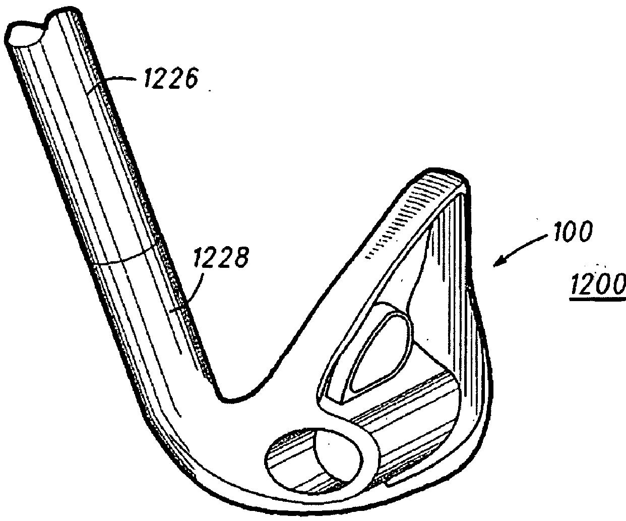
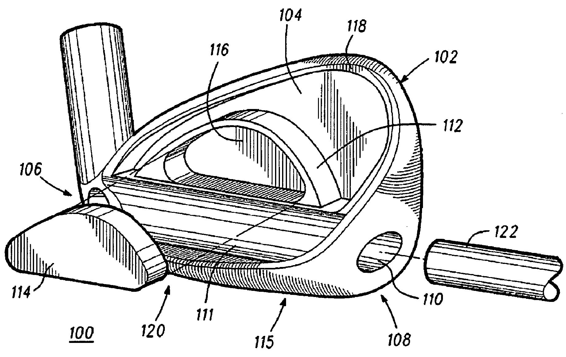
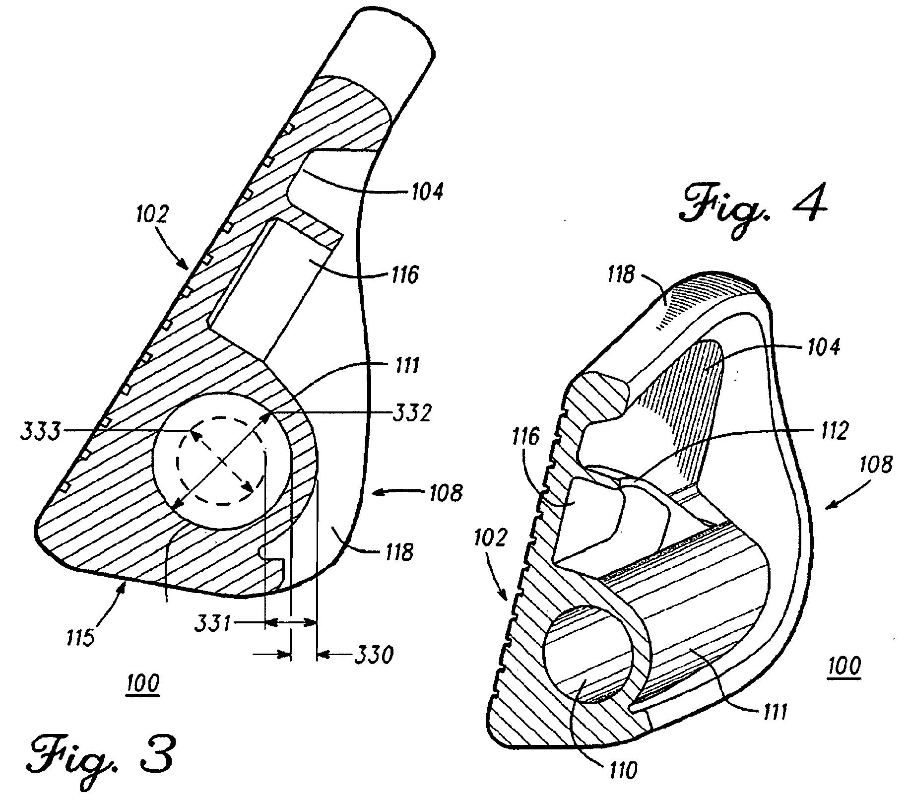
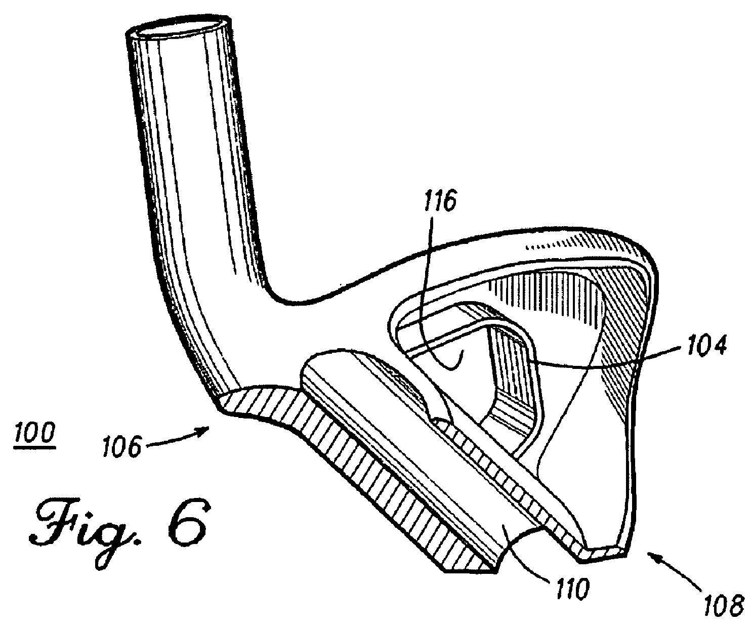
[0026] Among the various embodiments described herein, and as briefly described above, cavity 110 extends from heel region 106 to toe region 108. As can be seen among FIGS. 1 and 2, cavity 110 comprises an opening at toe region 108 and an opening at heel region 106. In a different embodiment, cavity 110 can comprise an opening at only one end, for example, merely a single opening at toe region 108 or a single opening at heel region 106. Furthermore, as best seen in FIG. 1, cavity 110 comprises an opening size commensurate with or slightly smaller than the size of filler material 122 that inserts into cavity 110. In some embodiments, however, cavity 110 opening can comprise a small opening or access point into cavity 110 to accommodate an injection device that can inject, for example, an expandable type of filler material 122. In such an embodiment, cavity 110 can be essentially closed at both ends except for the small opening or access point into cavity 110. Moreover, such an opening or access point into cavity 110 can be located at both or either toe region 108 end and heel region 106 end.[0027] Continuing with cavity 110, and among the various embodiments described herein, cavity 110 can comprise a number of configurations depending on the needs of the user or golfer. In general, cavity 110 can extend along a lower portion 120 of back face 104 of golf club head 100, and cavity 110 can provide bottom or sole weighting of golf club head 100. The housing to accommodate the dampening vibrational material can also provide bottom or sole weighting of golf club head 100. As can be seen from FIGS. 1 and 2, cavity 110 comprises an elongated, consistent “tubular” shape extending from heel region 106 to toe region 108. Moreover, cavity 110 comprises a wall 111 that defines a portion of cavity 110, as well as secondary cavity 116, and wall 111 extends away from back face 104 in an arcuate fashion from back face 104 towards a sole 115 of golf club head 100.
.
.
.
.
[0033] Continuing with the detailed description, filler material 122 can comprise different embodiments to provide a vibration dampening function. Filler material 122 comprises any material that can dampen vibrations encountered by golf club head 100 during use, and generally has a density that is less than the density of the main body of golf club head 100, although filler material 122 density can be greater in some embodiments. These materials can be natural or synthetic, or a combination of both. The materials can comprise polymers, rubbers, foams, gels, composites of each, or composites of each other. The materials may be solid and inserted into cavity 110, or they can be injected materials, for example, expandable foams. The materials can also be poured, sprayed, molded, or any other type of material or operation that ultimately results in filler material 122 occupying cavity 110. In one exemplary embodiment, filler material 122 comprises a composite of an elastomer or rubber type material having numerous metal ball bearings embedded throughout to create a composite rubber-metal matrix, and in another embodiment, a polymer may be used in place of the rubber to create a polymer-metal material. Among such embodiments, the rubber or polymer can completely encompass the metal material or bearings, such that the metal material or bearings do not intersect the surface of the insert, i.e., the metal material or bearings reside within the internal volume of the insert. In this manner, there is no metal to metal contact between the metal material or bearings and the internal cavity wall when the insert is positioned in the cavity; only the polymer or rubber/elastomer surface contacts the internal cavity wall.[0034] Some embodiments comprise filler material 122 occupying the entirety of cavity 110, but other exemplary embodiments comprise filler material 122 occupying only a portion of cavity 110, for example a coating of the interior walls of cavity 110. Additionally, a honeycomb-type material can be placed in cavity 110 that does not completely fill cavity 110 due to the air pockets within the honeycomb structure. It should be further noted that filler material 122 may be interchangeable with another type of filler material as the needs and/or preferences of an individual change.
[0035] In yet another exemplary embodiment of golf club head 100, filler material 122 comprises a first filler density and a second filler density, wherein the first filler density decreases from heel region 106 to centerline 224 (FIG. 2), the second filler density decreases from toe region 108 to centerline 224 (FIG. 2), and the second filler density comprises a similar density gradient as the first filler density. In still yet another exemplary embodiment, instead of the density gradient decreasing from either end towards centerline 224 (FIG. 2), the density gradient can increase from either end towards centerline 224 (FIG. 2).
Frankly, I go to as many demo days as I can and I hit as many irons as possible, yet I have never hit an iron and thought “wow, that vibration dampening feels good” (and trust me, it is not the result of only hitting pure shots). Sure, if I hit a blade from the 70’s the bad shots will feel much more severe than bad shots with modern equipment; but whether it is an A4, AP1, AP2, CG, FT, G10, i10, MP, MX, r7, S57, S9, X-20, X-22, or VR, I just don’t notice vibrations.
<
br>For me, it is more about ball flight and feeling confident as I look down at the club at address. Yes, it is probably because I am not good enough to notice, but I have always heard that good golfers want as much feedback as possible, which I assume means as little dampening as possible. Now, don’t get me wrong, I am sure that the sensitive testing equipment in golf labs can easily distinguish the vibrational characteristics of one club from another, but can the average golfer? Not this one.
Dave Dawsey – Watching Golf Iron Designs
PS – click here to check out iron patent posts