
One of the More Interesting Recent Putter Inventions
Today Nike Golf had a rather interesting patent application publish as US Pub. No. PING dynamically variable MOI driver.
Check this out!
The application describes the invention as:
A head for a ball striking device, such as a golf club head, includes a face member having a face with a striking surface configured for striking a ball and a rear surface opposite the striking surface, a weight member connected to the face member behind the rear surface of the face member, and a resilient member positioned between the weight member and the face member. The resilient member is connected to the rear surface of the face member to connect the weight member to the face member. The resilient member is compressible to permit energy and/or momentum to be transferred between the weight member and the face member through the resilient member during impact, including an off-center impact on the striking surface. Momentum transferred from the weight member to the face member during an off-center impact may reduce energy loss and twisting of the face on impact.
It goes on to explain:
BACKGROUND
[0002] Golf clubs and many other ball striking devices can encounter undesirable effects when the ball being struck impacts the ball striking head away from the optimum location, which may be referred to as an “off-center impact.” In a golf club head, this optimum location is, in many cases, aligned laterally and/or vertically with the center of gravity (CG) of the head. Even slightly off-center impacts can sometimes significantly affect the performance of the head, and can result in reduced velocity and/or energy transfer to the ball, inconsistent ball flight direction and/or spin caused by twisting of the head, increased vibration that can produce undesirable sound and/or feel, and other undesirable effects. Technologies that can reduce or eliminate some or all of these undesirable effects could have great usefulness in golf club heads and other ball striking devices.
.
.
.
BRIEF SUMMARY[0004] The following presents a general summary of aspects of the invention in order to provide a basic understanding of the invention. This summary is not an extensive overview of the invention. It is not intended to identify key or critical elements of the invention or to delineate the scope of the invention. The following summary merely presents some concepts of the invention in a general form as a prelude to the more detailed description provided below.
[0005] Aspects of the invention relate to ball striking devices, such as golf clubs, with a head that includes a face member having a face with a striking surface configured for striking a ball and a rear surface opposite the striking surface, a weight member connected to the face member behind the rear surface of the face member, and a resilient member comprising a resilient material positioned between the weight member and the face member. The resilient member is connected to the rear surface of the face member to connect the weight member to the face member. The resilient member is compressible to permit the weight member to transfer momentum to the face member through the resilient member upon an impact of the ball on the striking surface. The head may further include a hosel configured for connection of a shaft, the hosel being connected to the face member, rather than the weight member.
[0006] According to one aspect, the weight member is configured such that energy and/or momentum can be transferred between the weight member and the face member upon impact, including an off-center impact of the ball on the striking surface. The weight member may transfer momentum to the face member upon impact, and the amount of momentum transferred to the face member may increase incrementally with a lateral distance of a location of the impact away from a center of gravity of the face member.
.
.
.
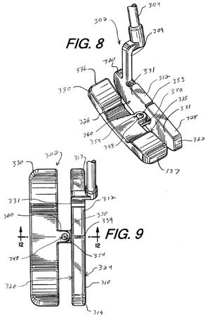
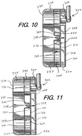
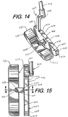
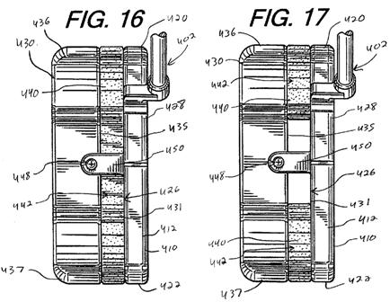
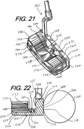
[0127] FIGS. 8-12 illustrate an embodiment of a ball striking head 302 that has a structure similar to the head 102 described above and shown in FIGS. 1-3. In the embodiment of FIGS. 8-12, the face member 328 and the weight member 330 are connected by a connection or connection point 348 formed by connection members 350, 360 connected to the face member 328 and the weight member 330, respectively. The structures of the face member 328 and the weight member 330 are otherwise substantially the same as the structures of the face member 128 and the weight member 130 of the head 102 of FIGS. 1-3, and such structures are not described again herein for the sake of brevity.[0128] In the embodiment of FIGS. 8-12, the face member 328 includes a connection member 350 that is formed by an arm 351 extending rearward from the rear side 326 or rear surface 331 of the face member 328, with a pin 352 extending upward from the arm 351. The weight member 330 has another connection member 360 that is formed by an arm 361 extending forward from the front surface 335 of the weight member, with a receiver 362 formed in the arm 361. The receiver 362 is configured to receive the pin 352 therein to connect the connection members 350, 360 together to form the connection point 348. In this embodiment, a fastener (such as a screw) 353 is also used to secure the connection between the connection members 350, 360. In another embodiment, a different type of fastener may be used, or no fastener may be used. Additionally, in other embodiments, the arrangement of the pin 352 and the receiver 362 may be transposed, such that the connection member 350 of the face member 328 has the receiver 362, and the connection member 360 of the weight member 330 has the pin 352. In other words, one of the connection members 350, 360 includes the pin 352 and the other of the connection members 350, 360 includes the receiver 362, in one embodiment. Other connection configurations may also be used, including the connections illustrated in FIGS. 14-22 and 26-41. The connection members 350, 360 in this embodiment form a joint 354 at the connection point 348. This joint 354 permits, or at least does not inhibit, transfer of energy and/or momentum between th
e weight member 330 and the face member 328, as described above with respect to the heads 102, 202 of FIGS. 1-3 and 5-7. It is understood that the joint 354 may include a washer or tensioning member that can be used to control or adjust the tension of the joint 354, to affect the degree of energy and/or momentum transfer upon impact. The connection members 350, 360 can serve to transfer momentum, including angular momentum, of the weight member 330 to the face member 328 in this embodiment.
Yes, they would like to also apply the concept to irons and woods.
Interesting, very interesting!