
New Nike Golf “Air” Golf Ball?
If the patent applications coming out of the Nike Golf R&D department are any indication, “The Oven” must be a place that welcomes unconventional thinking and ideas. How about some “adjustable dimples” as an example of unconventional thinking?
Today a Nike Golf patent application published as US Pub. No. 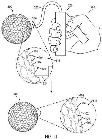
Yes, that is a hand pump being used to inflate the golf ball’s dimples! The application explains:
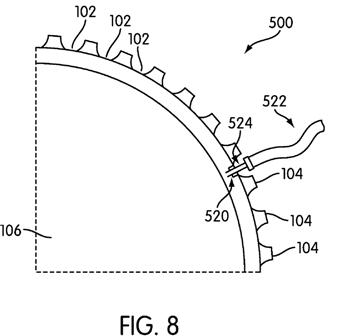
[0048] Another embodiment of a golf ball 500 is shown in FIGS. 8 and 9. Golf ball 500 includes a core 106, an intermediate portion 508, and an outer layer 110. Core 106 and outer layer 110 are as discussed above with respect to the embodiment shown in FIGS. 2 and 3. Golf ball 500 further includes a nipple 520, which is configured to be capable of interfacing with a nozzle 524 attached to a hose 522 which is ultimately attached to a pump. Nipple 520 allows for air (or other desired gas) to be introduced into intermediate portion 508.
[0049] Specifically, as shown in detail in FIG. 9, intermediate portion 508 may be an inflatable bladder that is located between core 106 and outer layer 110. Outer layer 110 overlays intermediate portion 508 in substantially all areas except at the base area 530 of a dimple 102, where intermediate portion 508 is the outermost structural layer. Intermediate portion 508 includes a top boundary layer 516, a bottom boundary layer 518, and connectors 532 and connectors 534 between top boundary layer 516 and bottom boundary layer 518. Areas 536 are open pockets into which gas may be introduced.[0050] Intermediate portion 508 has a first configuration 512. First configuration 512 is associated with first dimple depth 502, and a first dimple volume. While golf ball 500 is in first configuration 512, open pockets 536 may contain a first amount of gas. The first amount of gas creates a first pressure in the pockets 536. The first pressure is a pressure that is at least sufficient to maintain the structural integrity of golf ball 500 during use in a normal round of golf.
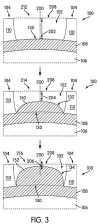
[0051] When additional gas is introduced into pockets 536, intermediate portion 508 changes from first configuration 512 into a second configuration 514. Second configuration 514 is associated with a second dimple depth 504, and a second dimple volume. In the specific embodiment shown in FIG. 9, intermediate portion 508 changes into second configuration 514 when sufficient additional gas is introduced into pockets 536 so as to create a second pressure therein. The second pressure should be sufficient to cause top boundary layer 516 to expand upward into dimple 102. When this occurs, certain of the connectors 534 elongate by stretching in order to retain the connection between the bottom boundary layer 518 and the new location of the top boundary layer 516. Other connectors 532 do not stretch, because outer layer 110 overlaps intermediate portion 508 in such a manner that top boundary layer 516 may only expand upward at the bottom surface 530 of dimple 102. When top boundary layer 516 of intermediate portion 508 expands upwards, it creates new bottom surface 550 of dimple 102. Second dimple height 504 is therefore the distance between new bottom surface 550 and line 208.[0052] Each of the different embodiments shown in FIGS. 1-9 includes a mutable material that is configured to change in a manner so as to alter the dimple depth and dimple volume. In the embodiment shown in FIGS. 8 and 9, the mutable material comprises top boundary layer 516, which is part of a flexible inflatable bladder. In such embodiments, the mutable material may be (for example) an elastomer having sufficient flexibility to deform under the second pressure. In other embodiments, the mutable material may be a solid polymeric material. For example, each of intermediate layer 108 in golf ball 100, portion 308 of cover layer 310 on golf ball 300, and portion 408 of cover layer 410 on golf ball 400 may each respectively be made of a continuous polymer material.
.
.
.
[0059] FIG. 11 shows an alternative embodiment of the method. As was discussed with respect to FIGS. 8 and 9, golf ball 500 may include intermediate portion 508 that changes configuration in response to a change in internal gas pressure. Golf ball 500 therefore, first, exists in first configuration 512 associated with first dimple depth 502. The gas pressure in pockets 536 may then be increased by introducing additional gas into pockets 536 through nipple 520. Specifically, a golfer may use a hand 528 held pump 526, having hose 522 and nozzle 524, to introduce additional gas. The additional gas may be air, sucked into the pump 526 from the atmosphere. Alternatively, for example, the additional gas may be a desired inert gas contained in a reservoir (not shown) in the pump 526. One or more golf ball(s) 500 may be sold in a kit along with pump 526 and one or more such reservoirs. As a result of the increased gas introduced by pump 526, the internal pressure in pockets 536 increases, causing golf ball 500 to achieve second configuration 514 associated with second dimple depth 504.
[0060] Although several embodiments of external stimuli, such as heating or changing gas pressure, are discussed above, the method of the present disclosure may generally include any external stimulus that can affect a change in the mutable material. For example, external stimuli such as radiating (even without heating), wetting, physical pressure, or exposure to a specific chemical composition are all methods of inducing a change in a polymeric material that may be used in the present method.[0061] Finally, FIG. 12 shows how the change in dimple depth affects the play characteristics of the golf ball. As was discussed above, a golf ball having shallow dimples will generally experience increased loft, and so fly along a higher flight path. On the other hand, a golf ball having deeper dimples will generally fly along a lower flight path. Golfer 602 may therefore customize the flight path golf ball 100 takes, all other factors being equal. Specifically, when golf ball 100 is in first configuration 212, golf ball 100 will generally take a first flight path 608 after being stuck by golf club 600 under generally dry conditions and with a typical swing speed not exceeding 100 mph. First flight path 608 will generally achieve increased vertical distance 612 at its peak, and slightly increased horizontal distance 606. First flight path 608 is generally symmetrical about its peak, the shifted peak shown in FIG. 12 is exaggerated for clarity.
[0062] On the other hand, when golf ball 100 is in second configuration 214, it will generally take second flight path 610, assuming the same conditions as first flight path 608. Second flight path 610 will generally achieve a lower vertical distance 614 at its peak, and very slightly less horizontal distance 606. Golfer 602 may therefore choose which configuration is most advantageous to the specific conditions under which the round of golf is being played.
Props to them if they can pull it off. Unfortunately my golf balls seem to find enough cart path bounces that I would be afraid of getting a flat.
David Dawsey – Keeping an Eye on Golf Ball Technology
PS – click HERE to read about a Nike dimple that changes with the weather.