
My Game is Not Ready for This Golf Glove
Interesting golf glove inventions do not come along everyday. In fact, the last interesting golf glove invention that I can remember was the Acushnet acupuncture based golf glove. Well, last week an interesting golf glove patent issued that may be a little too advanced for most golfers. After all, I have so many swing thoughts racing through my head that I can’t worry about what my golf glove is telling me. Are you ready for a glove like this?
FIG. 1 shows the force distribution at the upper reversal point of the swing, arrow 1 symbolizing the weight force of the club at the center of gravity, the arrows 2 symbolizing the supporting force of the thumbs and the arrows 3 symbolizing the force on the inner surface of the left hand.
FIG. 1 illustrates that, even in the case of a completely relaxed gripping pressure, the weight of the club must be downwardly supported by both thumbs at the upper reversal point of the swing. As a result of the fact that the center of gravity of the club is at a considerable distance from the grip, the force on the thumbs is intensified as a result of a lever effect. Therefore, arranging a sensor in the thumb results in incorrect signaling.
FIG. 1 also illustrates that a great force is exerted on the inner surface of the hand at the upper reversal point of the swing since the inner surface of the left hand upwardly supports the weight of the club. This force is even greater than the force on the thumbs since the only upwardly effective force occurs at this point when the forces are in equilibrium. Therefore, arranging a sensor on the inner surface of the hand likewise results in incorrect signaling at the reversal point of the swing.
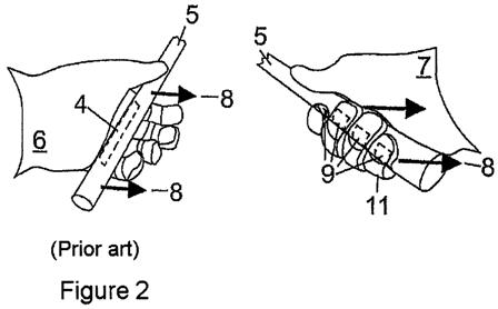
However, the following disadvantages of a sensor 4 on the inner surface of the hand of a golf training glove, which are explained with reference to FIG. 2, are far more serious:
With a correct swinging technique, the club 5 should be pushed away with the left hand 6 at the beginning of the swing and not pulled away with the right hand 7. As a result of incorrectly pulling away with the right hand 7, the fingers automatically tense in order to counteract the inertia of the club 5, while the correct initiation of the swing with the left hand 6 does not build up any harmful stress since all of the fingers can remain relaxed. However, with the correct technique for initiating the swing, a force is exerted on the sensor 4 on the inner surface of the hand as a result of the inertia of the club counter to the direction of movement indicated by the arrows 8 during the upswing, with the result that the sensor 4 is triggered even with a completely relaxed, correct grip. If, in contrast, sensors 9 are installed in the glove fingers 11 of the right hand 7 according to the invention, the incorrect technique for initiating the swing triggers these sensors 9, while the correct swinging technique would not trigger the sensors.
The basic design of a golf training glove according to the invention is illustrated for different sensor technologies in FIGS. 3 and 4 for a left glove 12.
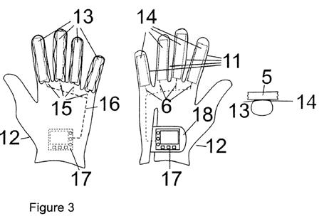
FIG. 3 shows a glove 12 according to the invention having electrical sensors 13 which are arranged on the inside of the glove fingers 11 over the entire length of the latter. The sensors 13 are situated in pockets whose outer skin 14 is indicated on the right of the figure. The connections 15 of the sensors 13 are connected to evaluation electronics 17 by means of connecting lines 16, said evaluation electronics being accommodated in a closure 18 for the glove 12 on the top side of the latter.
FIG. 4 shows a glove 19 in which air cushions 21 of pneumoelectrical sensors 21, 24 are situated only in the first two segments of the glove fingers 11. An elastic bead 25 surrounds the air cushions 21. The club 5 rests on the bead 25 and the air cushions 21. The air cushions 21 are connected to one another, such that they bridge the front two segments of each glove finger, by means of tubes 22. A respective further tube 23 respectively connects each pair of air cushions in a glove finger 11 to an electropneumatic converter 24, each converter 24 in turn being connected to the evaluation electronics 17 in the glove closure 18 by means of electrical connecting lines 16.
As regards the sensors of the glove 12 for the left hand 6, which is illustrated in FIG. 4, all fingers (apart from the thumb) uniformly enclose the grip and can thus be weighted equally.
If, for reasons of cost, only small sensors, that is to say those with only one air cushion for each sensor, are used, they should be in the upper segments of the glove fingers 11. As regards the sensors of the glove for the right hand 7, one sensor in the glove finger 11 for the little finger can be dispensed with for reasons of cost since, in the vast majority of gripping techniques, said finger does not rest on the club.
Irrespective of the technology used, the sensors 21, 24 for each finger provide an analog measured value which is processed further in the evaluation electronics 17 using a digital microcontroller following analog/digital conversion. The task of these evaluation electronics 17 is to use the pressure values determined for the individual fingers as a basis for deciding whether the gripping pressure has exceeded a critical value and to signal this using light, sound or vibration.
The question as to whether an alarm should be triggered depends on the threshold value and on the period of time for which this value is exceeded. It is possible to define a separate threshold value for each individual finger. In any case, at least one joint threshold value for all sensors 21, 24 in the glove fingers 11 can be set in a continuously variable manner or in stages in order to set particular degrees of difficulty (beginner, advanced player). In addition, a distinction may be made between the threshold value for the glove 12 for the left hand 6 and that for the right hand 7.
So that random measurement errors (pressure peaks) and situations in which the threshold value is exceeded only briefly but in a desirable manner (for example when contact is made with the ball or ground) do not trigger incorrect signaling, only situations in which the threshold value is exceeded for a longer period of time should initiate signaling. For this purpose, the sensor values measured can be filtered using a low-pass filter, for example.
FIG. 5 illustrates the basic block diagram of evaluation electronics 17. A microcontroller which is denoted overall using 27 is used to process the measured values and coordinate the input and output elements 26, 28. The inputs are made using buttons which can be seen in FIGS. 3, 4 and 6, while output is effected using optical and acoustic signaling means 28, for example a display or loudspeaker.
A user profile is input to a memory 29, for example a “look-up table”, using the buttons of the evaluation electronics 17. The user profile comprises individual threshold values for the measured values recorded by each sensor 21, 24 as well as values for scaling and temporally smoothing the measured values from each sensor 21, 24. The threshold value comparison of the measured values from the sensors 21, 24 is carried out in comparators 32 for the signal path of each individual sensor. Low-pass filters 31 for the temporal smoothing as well as attenuation and amplification elements 33 for the scaling are also situated in the signal path. If one of the comparators 32 determines that the measured value exceeds the threshold value predefined for the respective user profile, this is indicated for each signal path using the signaling means 28. A voltage-controlled oscillator 34 is connected upstream of the acoustic signaling means 28. The voltage-controlled oscillator 34 generates output voltages at different frequencies on the basis of the output signal generated by the comparator 32, said output voltages generating sounds of different levels in a loudspeaker, for example. Therefore, different acoustic signals are generated depending on the extent to which the threshold value is exceeded.
In addition, the outputs of all comparators 32 are connected to an OR circuit 35. The latter likewise uses the further optical/acoustic signaling means 28 to trigger an alarm if only one of the comparators 32 determines that the threshold value has been exceeded.
On the input side, the evaluation electronics 17 have, for each measurement channel, an analog/digital converter A/D which converts the analog measurement signals from the pneumoelectrical converter 24 into digital signals downstream of signal conditioning 36.
The following factors are feasible, for example, as scaling factors X1-X4 for the attenuation and amplification elements 33, where X1 is assigned to the measured values from the sensor of the index finger, X2 is assigned to the measured values from the sensor of the middle finger, X3 is assigned to the measured values from the sensor of the ring finger, and X4 is assigned to the measured values from the sensor of the little finger: X1=1.0 X2=1.0-1.2 X3=1.0-1.25 X4=0.8-0.95
Attenuation of the little finger is expedient since the club grip exerts an intensified pressure on the little finger during initiation of the swing. So that this additional pressure on the little finger is not incorrectly detected as being an excessively high gripping pressure by the comparator 32, the measured value at the little finger is attenuated, while the measured values at the middle and ring fingers, which are weaker than the index finger, are amplified slightly in comparison with that at the index finger.
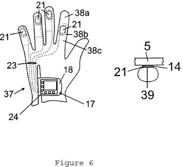
FIG. 6 shows a glove 37 in which the electropneumatic sensors 21, 24 are arranged in such a manner that the pressure exerted on the grip by the player can be detected in a manner largely independent of an ideal grip. The fingers 11 of the glove 37 are subdivided into three segments 38a-c, the air cushions 21 of the sensors 21, 24 being arranged in the first segment 38 a of the glove fingers for accommodating the little finger, the ring finger and the middle finger, and the air cushion 21 being arranged in the second segment 38b of the glove finger for accommodating the index finger. The individual air cushions 21 are connected to the converters 24 by means of tubes 23. The pneumoelectrical converters 24 provide analog signals which are processed further in the evaluation electronics 17 according to FIG. 5 following analog/digital conversion.
The air cushions 21 are filled with gas permeable foam 39 which keeps the air cushions 21 in a defined form. In the case of this glove 37 too, the evaluation electronics 17 are integrated in the closure 18 and accordingly have input and output elements 26, 28.
FIG. 7 finally shows a side view of evaluation electronics 17 which are releasably connected to the glove 12, 19 or 37. For this purpose, a base 44 which is adapted to the contour of the back of the hand is fastened to the top side of the glove 12, 19, 37. The housing 45 which accommodates the evaluation electronics 17 is releasably hooked to the base 44. For this purpose, at least one of the hooks 46 is designed such that it can be moved counter to the force of a spring 47. The movable hook 46 can be displaced by actuating a pin 48 which extends through the wall of the housing 45, with the result that the housing 45 is released.
The pneumoelectrical converters 24 are coupled to the tube lines 23 by virtue of the end sections of the tube lines engaging in corresponding receptacles of the converters 24. In the case of electrical sensors in the glove fingers, the electrical lines leading from the sensors open into contact areas on the surface of the base 44 which interact with corresponding contact areas on the underside of the housing 45.
The removable evaluation electronics 17 can continue to be used when the glove is worn out. Only the relatively inexpensive air cushions 21 including the tubes 23 welded to them are replaced.
I often see golfers seize up with paralysis by analysis, and this glove could only make things worse.
Dave Dawsey – Keeping an Eye on Golf Glove Inventions
PS – check out other golf glove related posts here