
Mizuno Granted Patent on the Fast Track Design
If you read the Golf-Patents blog then you are probably familiar with Mizuno’s Fast Track adjustable weight positioning system. Today Mizuno was granted a patent on this unique weight channel system. The patent is USPN 7611424 titled “Golf Club Head and Golf Club” and describes the invention as:
A golf club head of the wood-type, including: a body defining an interior cavity and including a ball-striking face, a sole, a crown, and a ribbon extending rearwardly from the face; an elongated groove that extends along a portion of the ribbon; a weight slidably disposed in the elongated grove; and a fastener affixed to the weight capable of selectively fixing a location of the weight.
The patent goes on to explain:
Disclosed herein is a golf club head of the wood-type, including: a body defining an interior cavity and including a ball-striking face, a sole, a crown, and a ribbon extending rearwardly from the face; an elongated groove that extends along a portion of the ribbon; a weight slidably disposed in the elongated grove; and a fastener affixed to the weight capable of selectively fixing a location of the weight.
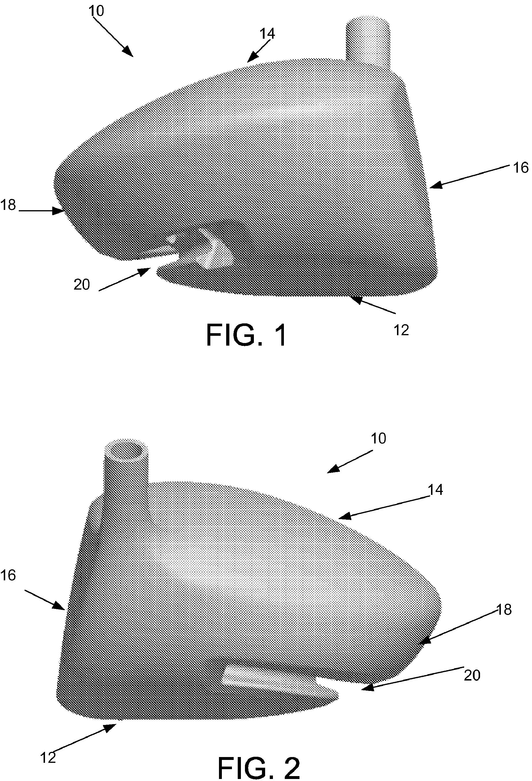
Referring now to FIGS. 1 and 2, a golf club head 10 in accordance with an exemplary embodiment is illustrated. The club head 10 is of the wood type, and is preferably a metal wood including a body and hosel. In exemplary embodiments, the club head 10 can be formed in a conventional manner, such as welding components together as is known in the art. The club head 10 includes a sole 12, a crown 14, a ball-striking face 16, and a ribbon 18 extending rearwardly from the ball-striking face 16. The ribbon 18 includes an elongated groove 20 that extends along a portion of the ribbon 18. In exemplary embodiments, the elongated groove 20 may be located on a lower portion of the ribbon 18. The elongated groove 20 may extend around the entire ribbon 18, from the heel to the toe of the club head 10, or any portion thereof.
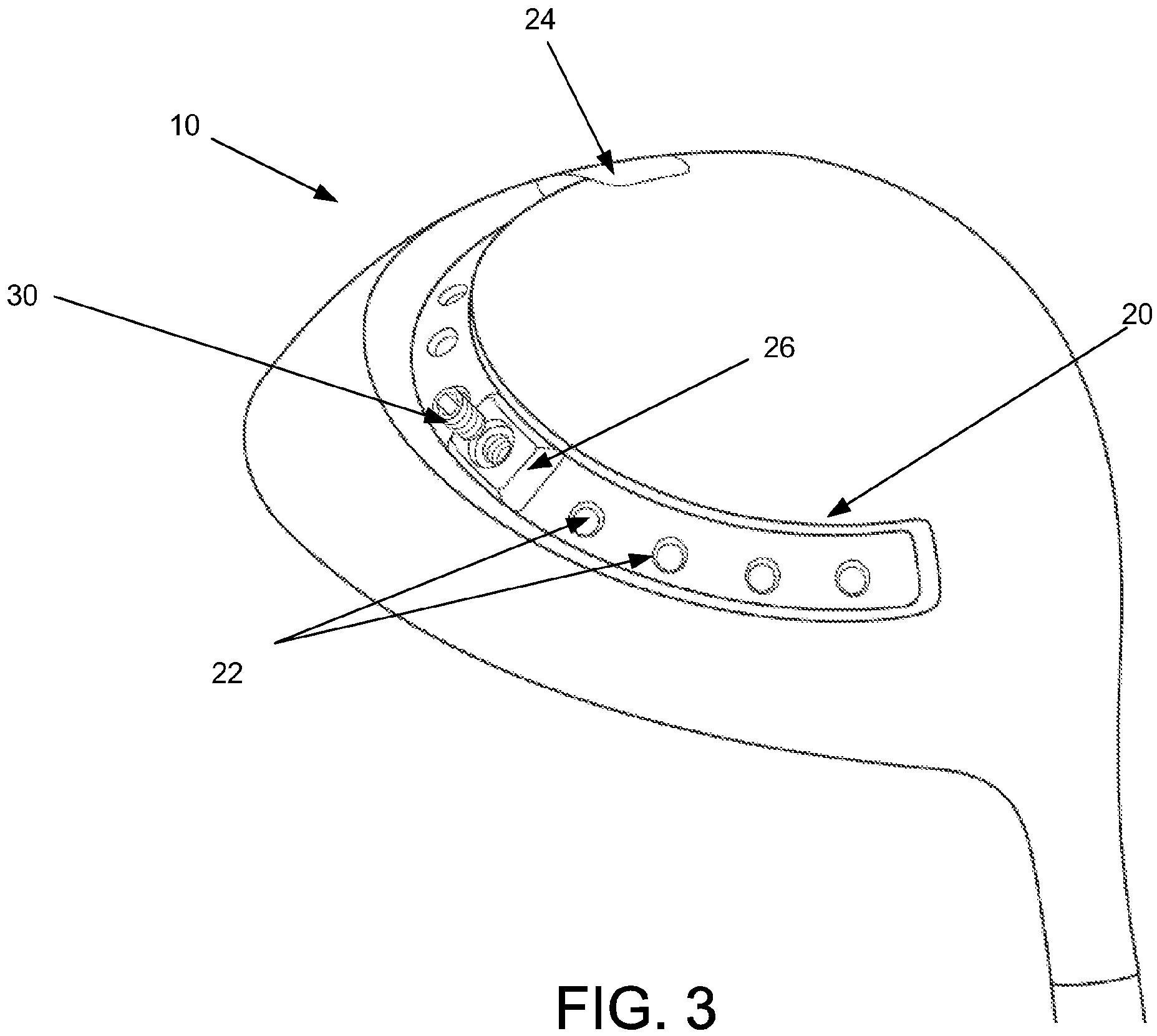
Turning now to FIG. 3, a perspective view of the bottom of the club head 10 is illustrated. As shown, the elongated groove 20 includes a plurality of recesses 22 disposed on an inner surface of the elongated groove 20. The recesses 22 may be of varying width and depth and may be spaced evenly along the elongated groove 20. In an exemplary embodiment, the recess 22 may be sloped on both sides to guide the weight to a predetermined position in the elongated groove 20. A receiving slot 24 is located adjacent to one end of the elongated groove 20 and the receiving slot 24 has an aperture larger than the outer portion of the elongated groove 20. The elongated groove 20 is designed to house one or more weights 26 that can be repositioned by a user. The number of weighs 26 in the elongated groove 20 is less than the number of recess 22 disposed along the inner portion of the elongated groove 20. In one embodiment, the weights 26 are inserted into the elongated groove 20 through the receiving slot 24 by the manufacture of the club such that the weights are not removable from the elongated groove 20.
Continuing with reference to FIG. 3, the weight 26 is slidably disposed in the elongated groove 20. In addition, the receiving slot 24 includes a stop that is positioned in the receiving slot 24 to prevent the weight 26 from being removed from the elongated groove 20. The weight 26 includes a fastener 30 that is designed to selectively fix the position of the weight 26 in the elongated groove. In an exemplary embodiment, the fastener 30 is a bolt that extends through the weight 26 and engages one of the recesses 22 on the inner surface of the elongated groove 20. The fastener 30 is designed to prevent the weight 26 from moving in the elongated groove 20 during the swinging of the golf club during which the weight 26 can be subjected to several strong forces.
In exemplary embodiments, the club head 10 may include a plurality of weights 26 that are slidably disposed in the elongated groove 20. The weights 26 are inserted into the elongated groove 20 through the receiving slot 24 and a stop is placed in the receiving slot 24 to prevent the weights 26 from being removed from the elongated groove 20. The weights 26 can be placed in a uniform weight distribution pattern in the elongated groove 20 or in a variable distribution so that more weight can be provided in a particular region of the club head 10, either rearwardly or more toward the toe or heel portion as desired. In exemplary embodiments, the weight 16 can be formed of any material such as metal or fiber reinforced plastic.
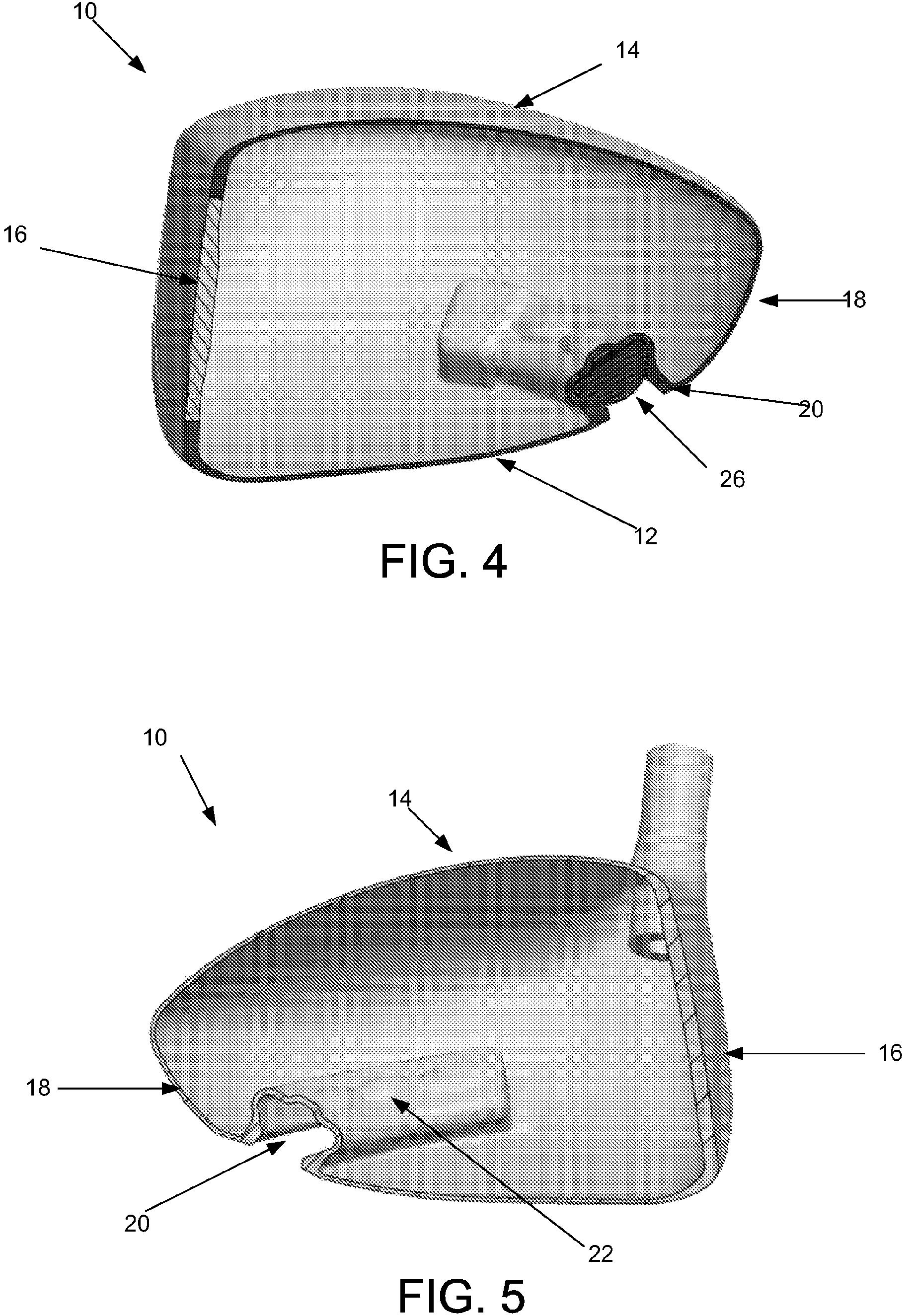
Turning now to FIGS. 4 and 5, cross sectional views of the club head 10 are illustrated. As shown, the elongated groove 20 may have a dovetail shape that is designed to allow the weights 26 to freely slide in the elongated groove 20 but prevent the weights 26 from coming out of the elongated groove 20. In other exemplary embodiments, the elongated grove 20 may have another suitable shape. The weights 26 may have a shape designed to be at least partially complementary to the shape of the elongated groove 20. Additionally, the one or more weights 26 may all have the same mass or different masses. For example, three weights 26 may be disposed in the elongated groove 26 and the outer two weights may have the same mass while the central weight has a different mass.
By changing the location of the weights 26 in the elongated groove 20 the user can effectively change the performance of the club head 10. For example, an increased weight at the bottom of the head provides a higher trajectory to a ball struck by the club. Peripheral weighting increases the moment of inertia and the resistance to rotation of the club, particularly when a ball is struck outside the center of the striking face.
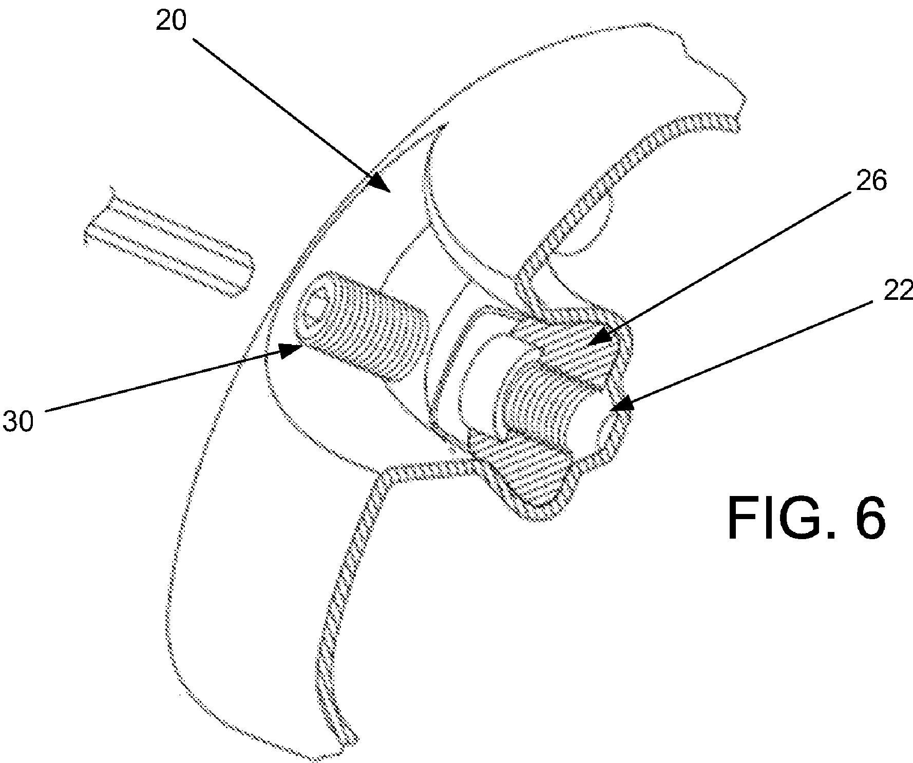
Referring now to FIGS. 6 and 7 a cross sectional view of a portion of the wood-type golf club head 10 and the fastener 30 are show, respectively. The fastener 30 is designed to affix the location of the weight 26 in the elongated groove 20 by engaging both the weight 26 and the recess 22. In one embodiment, the fastener 30 may be a threaded bolt 30 which extends through the weight 26 and contacts the recess 22. In another exemplary embodiment, the fastener 30 may be a spring bolt, a cross section of a portion of which is illustrated in FIG. 7. The spring bolt 30 includes a compression portion 36 disposed in the center of a thread portion 34 of the spring bolt. The thread portion 34 is designed to compress when in contact with a receiving member 32 and thereby prevent the spring bolt 30 from turning freely in the weight 26.
Pretty cool.
Dave Dawsey – Keeping an Eye on Adjustable Golf Driver Patents
PS – click HERE to check out additional posts regarding driver inventions