
Man You Sheared the Heck Out of that Ball
I bet you haven’t uttered those words on a tee box before. In the future golfers may be thinking more about the shear force imparted on a golf ball by a bad swing. Recently Nike Golf had a patent application publish as US Pub. No. A golf ball includes an inner layer, an outer layer, and a cavity therebetween. A fluid, such as a viscous damping fluid, is placed in the cavity. When the ball is struck, the inner and outer layers rotate independently of one another. Indicia are provided on the inner and outer layers. An examination of the relative position of the indicia before the ball is struck and after the ball is struck can yield data that indicate the shear force of the stroke.
What, independently rotating layers! That sounds slightly complicated.
The application explains:
[0002] There are various systems that exist that allow a person to measure the shear force imparted to a golf ball upon impact with a golf club. Most of these systems determine club head speed, which is then used to estimate or calculate shear force.
[0003] Conventionally, club head speed can be measured with various equipment or methods. The club head speed can be measured directly through a sensor on the club or a camera-based system. Alternatively, the club head speed could be measured indirectly through the use of an impact mark on the club or ball. Other conventional systems can be used to otherwise calculate club head speed. However, each of these systems requires the use of an external sensor or other piece of equipment.
[0004] The knowledge of the shear force generated by a particular stroke can be useful for many things. It can be used, for example, to select a particular ball. Alternatively, it can be used to change a golfer’s swing mechanics to change the shear force generated by his or her swing profile.
[0005] In the conventional systems, while there are conventionally known structures and methods available to make the calculation, such systems are not typically used by an ordinary golfer. An ordinary golfer may be dissuaded from using the systems because they are expensive or complicated.[0006] Therefore, it is desirable to consider systems for measuring shear force that are relatively inexpensive and that can be used either in a professional context or as a typical golfer.
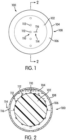
[0027] FIGS. 1 and 2 show a first embodiment of a golf ball 100. Golf ball 100 includes an inner layer 102 and an outer layer 104. Inner layer 102 and outer layer 104 are spaced from one another, forming cavity 106. A fluid is present in cavity 106. Inner layer 102 and outer layer 104 may be capable of rotating independently of one another.
[0028] The fluid in cavity 106 can be a liquid or a gas. In a simplified form, the gas can be the standard composition of air. However, if air or another gas is used, it may be desirable to insert the gas under pressure in order to keep inner layer 102 and outer layer 104 spaced from one another. Alternatively, the fluid can be a liquid. The liquid can be a high viscosity liquid that damps the relative rotation of inner layer 102 and outer layer 104.
.
.
.
[0030] In a commercial version, the outer layer, and in particular, outer surface 108 of outer layer 104, is configured to be struck by a golf club. Accordingly, outer layer 104 may include various dimples, frets or lands, projections, printing, or any other features that a designer thinks would be desirable in affecting the flight path of the ball 100. Outer layer 104 may be designed to be scuff resistant. In the embodiment of FIGS. 1 and 2, outer layer 104 is translucent. It may be desirable for outer layer 104 to be transparent or at least translucent.
.
.
.
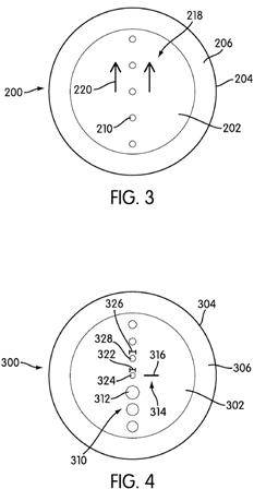
[0032] First indicia 110 is applied on inner layer 102. First indicia 110 includes a plurality of circles or dots 112. Second indicia 114 comprises a line 116 applied on outer layer 104. The application of first indicia 110 to inner layer 102 and application of second indicia 114 to outer layer 104 can be performed by any technical means that is available or desirable based on the materials used for first indicia 110, second indicia 114, inner layer 102, and outer layer 104. In some cases, the indicia can be applied to the respective layer by printing it on the top of the layer, as shown in FIGS. 1 and 2. Alternatively, the indicia may be embossed on the respective layer and may be even with the outer surface of the respective layer.[0033] FIG. 3 shows a top view of an alternative embodiment of a golf ball 200. Golf ball 200 includes an inner layer 202 that has the same characteristics as inner layer 102 and an outer layer 204 that has the same characteristics as outer layer 104. Inner layer 202 and outer layer 204 are spaced from one another, forming cavity 206 that has the same characteristics as cavity 106, including being filled with a similar fluid. Inner layer 202 and outer layer 204 may be capable of rotating independently of one another.
[0034] First indicia 210 is applied on inner layer 202 and has the same basic characteristics as first indicia 110. First indicia 210 includes a plurality of circles or dots 212. Ball 200 may include second indicia, but this is not shown in FIG. 3. Ball 200 also may include third indicia 218. Third indicia 218 may include two arrows 220. Third indicia 218 may be positioned to assist a user in positioning ball 200 in an appropriate or desired orientation of ball 200 when ball 200 is to be struck by a golf club when used in the method disclosed in greater detail below. Third indicia 218 is shown only in the embodiment of FIG. 3, but it can easily be added to any of the embodiments illustrated in other figures. Third indicia 218 can be imprinted or applied on either inner layer 202 or outer layer 204, whichever is deemed more desirable by the designer.
[0035] FIG. 4 shows a side view of an alternative embodiment of a golf ball 300. Golf ball 300 includes an inner layer 302 that has the same characteristics as inner layer 102 and an outer layer 304 that has the same characteristics as outer layer 104. Inner layer 302 and outer layer 304 are spaced from one another, forming cavity 306 that has the same characteristics as cavity 106, including being filled with a similar fluid. Inner layer 302 and outer layer 304 may be capable of rotating independently of one another.
[0036] First indicia 310 is applied on inner layer 302 and has the same basic characteristics as first indicia 110. First indicia 310 includes a plurality of circles or dots 312. The circles or dots 312 differ from the circles or dots 112 of the first indicia 110 in that they have gradually increasing diameters. For example, diameter 322 of first exemplary dot 324 is smaller than diameter 326 of adjacent second exemplary dot 328. Second indicia 314 is applied to outer layer 304 and has the same basic characteristics as second indicia 114. Second indicia 314 may comprise a line 316.
[0037] The use of a series of differently sized dots as first indicia 310 may provide a mechanism to designate or determine the initial or first relative position of first indicia 310 and second i
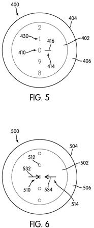
ndicia 314. For example, a user may examine ball 300 to determine the relative position of first indicia 310 and second indicia 314. The user may rotate inner layer 302 relative to outer layer 304 until the smallest dot 324 is generally aligned or positioned adjacent line 316 in a particular relative position. The user may cause this rotation via rolling or shaking or any other available mechanism or method as may be desirably used. For example, in this or any of the other embodiments, a magnetic element could be embedded or positioned in the inner layer and a magnet could be used to move the inner layer relative to the outer layer until first indicia 310 is positioned in alignment with second indicia 314. This alignment of the first indicia 310 and second indicia 314 may be useful when one of the methods disclosed below is used.[0038] FIG. 5 shows a side view of an alternative embodiment of a golf ball 400. Golf ball 400 includes an inner layer 402 that has the same characteristics as inner layer 102 and an outer layer 404 that has the same characteristics as outer layer 104. Inner layer 402 and outer layer 404 are spaced from one another, forming cavity 406 that has the same characteristics as cavity 106, including being filled with a similar fluid. Inner layer 402 and outer layer 404 may be capable of rotating independently of one another.
[0039] First indicia 410 is applied on inner layer 402 and has the same basic characteristics as first indicia 110. First indicia 410 includes a plurality of numbers 430. The numbers 430 can be a series of gradually increasing numbers, for example increasing from 0 to 9 as shown in FIG. 5. Second indicia 414 is applied to outer layer 404 and has the same basic characteristics as second indicia 114. Second indicia 414 may comprise a line 416.
[0040] The use of a series of gradually increasing numbers as first indicia 410 may provide a mechanism to designate or determine the initial or first relative position of first indicia 410 and second indicia 414. For example, a user may examine ball 400 to determine the relative position of first indicia 410 and second indicia 414. The user may rotate inner layer 402 relative to outer layer 404 until a desired number 430, such as the number 0 as shown, is generally aligned or positioned adjacent line 416 in a particular relative position. The user may cause this rotation via rolling or shaking or any other available mechanism or method as may be desirably used. This alignment of the first indicia 410 and second indicia 414 may be useful when one of the methods disclosed below is used.
[0041] FIG. 6 shows a side view of an alternative embodiment of a golf ball 500. Golf ball 500 includes an inner layer 502 that has the same characteristics as inner layer 102 and an outer layer 504 that has the same characteristics as outer layer 104. Inner layer 502 and outer layer 504 are spaced from one another, forming cavity 506 that has the same characteristics as cavity 106, including being filled with a similar fluid. Inner layer 502 and outer layer 504 may be capable of rotating independently of one another.
[0042] First indicia 510 is applied on inner layer 502 and has the same basic characteristics as first indicia 110. First indicia 510 includes a plurality of circles or dots 512. In addition to the inclusion of circles or dots 512, first indicia 510 may include an alignment aid, such as arrow 532. Second indicia 514 is applied on outer layer 504 and has the same basic characteristics as second indicia 114. Second indicia 514 may comprise arrow 534.
[0043] The use of two arrows, one arrow 532 as a part of first indicia 510 and one arrow 534 as a part of second indicia 514 may provide a mechanism to define the initial relative position of first indicia 510 and second indicia 514. For example, a user may examine ball 500 to determine the relative position of first indicia 510 and second indicia 514. The user may rotate inner layer 502 relative to outer layer 504 until first indicia arrow 532 is generally aligned or positioned adjacent second indicia arrow 534 in a particular relative position. The user may cause this rotation via rolling or shaking or any other available mechanism or method as may be desirably used. This alignment of the first indicia 510 and second indicia 514 may be useful when one of the methods disclosed below is used.
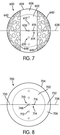
[0044] FIG. 7 shows a side view of an alternative embodiment of a golf ball 600. Golf ball 600 includes an inner layer 602 that has the same characteristics as inner layer 102 and an outer layer 604 that has the same characteristics as outer layer 104. Inner layer 602 and outer layer 604 are spaced from one another, forming cavity 606 that has the same characteristics as cavity 106, including being filled with a similar fluid. Inner layer 602 and outer layer 604 may be capable of rotating independently of one another.
[0045] First indicia 610 is applied on inner layer 602 and has the same basic characteristics as first indicia 510. First indicia 610 includes a plurality of circles or dots 612. In addition to the inclusion of circles or dots 612, first indicia 610 may include an alignment aid, such as line 636. Second indicia 614 is applied on outer layer 604 and has the same basic characteristics as second indicia 514. Second indicia 614 may comprise line 616.
[0046] As shown in FIG. 7, it may be desirable to restrict the rotation of the inner layer 602 relative to outer layer 604 such that the rotation only occurs on a single axis of rotation, such as axis 638, and restrict movement along any other axis. Such a restriction can be enforced by the inclusion of a guide on ball 600. As shown in FIG. 7, the guide includes first guide section 640 and second guide section 642. First guide section 640 and second guide section 642 are each secured to inner layer 602 so that neither can rotate with respect to inner layer 602. First guide section 640 and second guide section 642 are shown in FIG. 7 as being similar in material and design to a standard golf ball. The guide sections 640, 642 could instead be of the same material as the rest of outer layer 604 but simply secured to inner layer 602. As a further alternative, first divider 644 could be inserted between first guide section 640 and outer layer 604 and second divider 646 could be inserted between second guide section 642 and outer layer 604. First divider 644 and second divider 646 could be used alone, allowing first guide section 640 and second guide section 642 to independently rotate around axis 638.
.
.
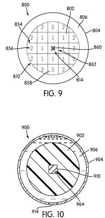
.[0050] FIG. 9 shows a side view of an alternative embodiment of a golf ball 800. Golf ball 800 includes an inner layer 802 that has the same characteristics as inner layer 102 and an outer layer 804 that has the same characteristics as outer layer 104. Inner layer 802 and outer layer 804 are spaced from one another, forming cavity 806 that has the same characteristics as cavity 106, including being filled with a similar fluid. Inner layer 802 and outer layer 804 may be capable of rotating independently of one another.
[0051] First indicia 810 is applied on inner layer 802 and has the same basic characteristics as first indicia 110. First indicia 810 includes a plurality of grid lines 854 and numbers 856 in squares 858 defined by grid lines 854. Second indicia 814 is ap
plied on outer layer 804 and has the same basic characteristics as second indicia 114. Second indicia 814 may comprise an X shape 860.
[0052] It may be desirable to use a numbered grid when it is desired, for example, to consider shear force applied along various axes or planes. In the embodiment shown in FIG. 9, outer layer 804 can be positioned so that second indicia 814 is positioned in a designated first indicia starting grid square, such as the starting square 862 marked with a 0. When the outer layer 804 moves with respect to inner layer 802, a user can determine the directionality and magnitude of the force depending on the final position of outer layer 804 relative to inner layer 802.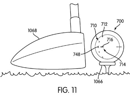
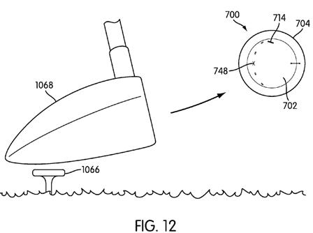
[0055] FIGS. 11-13 show a method of use for the golf balls and alternatives disclosed herein. FIGS. 11-13 show the use of golf ball 700 as shown in FIG. 8. The method is described in conjunction with that embodiment. However, any of the ball embodiments can be used in the method described.
[0056] As shown in FIG. 11, ball 700 may be positioned on a tee 1066. Ball 700 may alternatively be placed on the ground, on a tether, or otherwise positioned as may be desired by a user. As shown in FIG. 11, first indicia 710 includes plurality of dots 712 and alignment marking 748. Second indicia 714 includes a line 716 that is aligned with alignment marking 748. A first relative position of first indicia 710 and second indicia 714, such as the aligned position shown, may be selected for use as a starting position or for use at a first specified time. Ball 700 is then ready to be struck by club 1068. FIG. 11 shows the use of a driver or other wood as club 1068. Any club can be selected instead of the driver shown as may be desired by a user or for any other reason.
[0057] As shown in FIG. 12, when club 1068 strikes ball 700, inner layer 702 and outer layer 704 rotate independently of one another. As may be seen, second indicia 714 has rotated to a position away from first indicia alignment indicia 748. FIG. 12 is shown for illustrative purposes, and it is unlikely that any relative position of inner layer 702 and outer layer 704 will be examined or determined while ball 700 is in the air.
[0058] FIG. 13 shows a potential final rest position of ball 700. When ball reaches its final rest position or another designated position at a second specified time, ball 700 can be examined to determine the final or second relative position of first indicia 710 and second indicia 714. FIG. 13 shows one exemplary version of a second relative position. FIG. 13 shows that second indicia 714 is positioned generally adjacent the first indicia second dot 712 above first indicia alignment indicia 748. The use of a guide, such as first spindle 750 and second spindle 752, restricts rotation of outer layer 704 relative to inner layer 702 to one axis and may enable a less complicated analysis of the shear force applied to ball 700 upon impact by club 1068, as first indicia 710 and second indicia 714 will maintain a predictable range of relative positions.
[0059] Once the first relative position at a first specified time before being struck by the club and the second relative position at a second specified time after being struck by the club have been determined, the first relative position and the second relative position data can be used. The first relative position and the second relative position can be compared to one another. The first relative position and the second relative position can be compared with a database that indicates a particular shear force that yields the two relative positions. The database can take the form of a printed chart or other comparison data printed on paper. Alternative, the database can take the form of a database within a computer.
.
.
.
Very interesting. Wouldn’t a rotating outer layer dramatically reduce the spin? Sounds similar to putting Vasoline on a club face. It must be a practice ball.
David Dawsey – Keeping an Eye on Golf Ball Innovation
PS – click HERE to read about a spin indicating golf ball that changes colors