
Just What I Need, One More Thing to Look at as I Stand Over the Golf Ball
I am glad that Nike is getting into the golf ball IP arena because they don’t seem to be afraid to try to protect the “unusual.” Their latest golf ball related invention has to do with an alignment guide for a golf ball and it is pretty interesting. The invention is disclosed in a patent application that published this week as US Pub. No. 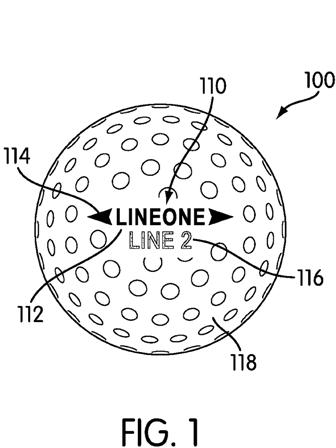
[0021] FIG. 1 shows an embodiment of a golf ball 100 with an indicia 110 disposed on a surface 118 of golf ball 100. Golf ball 100 may be any type of ball known in the art used for playing golf or training for golf, such as a solid ball or a wound ball. Golf ball 100 will typically include a core, one or more intermediate solid, viscous, or wound layers, and a cover.
[0022] Surface 118 may be any type of outer or outermost surface for a golf ball known in the art. Surface 118 may include the surface of the cover of golf ball 100, which cover may be made of a rubber, polymer, or plastic material. Surface 118 may also include any coating layers applied to the surface of the cover of golf ball 100. For example, the coating layer may include a paint layer, a sealing layer, or other type of coating. The cover of golf ball 100 may be any type of golf ball cover known in the art, such as a rubber, ionomer material, or a polyurethane material.
[0023] Surface 118 has a color visible to a golfer. The color of surface 118 may be considered to be the background color for indicia 110. For many golf balls, surface 118 has a white color. The precise shade of white of surface 118 may be selected from any shade of white. In other embodiments, surface 118 may have another color. Other common colors for golf balls include green, orange, and yellow, though any color may be used.
[0024] The color of surface 118 may be achieved by any means known in the art. For example, in some embodiments, the color of surface 118 may be provided by a paint layer, typically paint solids suspended in a polymer. The color of the paint layer is provided by the color of the paint solids or a mixture of colors provided by paint solids of multiple colors. In other embodiments, the color of surface 118 may be provided by particles mixed into the material of the cover layer of golf ball 100, such as titanium dioxide. In other embodiments, the color of surface 118 may be provided by a dye imparted to the cover layer of golf ball 100 using any method known in the art, such as sublimation or infusion dying techniques. In other embodiments, the perceived color of surface 118 by the golfer may be a combination of these and other colored outer layers of the ball. For example, the cover material may include titanium dioxide and a coating layer may include silvered metallic particles. The combination of these colored layers may impart a bright sparkling white color appearance to surface 118.
[0025] Indicia 110 may be marked on surface 118 or a coating disposed on surface 118 using any method known in the art, such as printing, dying, pad printing, stamping, ink jet printing, masking, screen printing, painting, adhered as a label, or the like. In some embodiments, indicia 110 may be locally integrated with surface 118 by a dying process such as sublimation dying or infusion dying. For clarity, in this discussion “printing” may be used to refer to any of the methods that may be used for depositing indicia 110, parts of indicia 110, and/or components of indicia 110 regardless of the actual method used. For example, a “line of printing” may denote a series of printed characters, dyed characters, etc.
[0026] Indicia 110 may be formed from any type color medium known in the art, such as dye, paint, and ink. In some embodiments, more than one type of color medium may be used. Any subpart or component of indicia 110 may be monochromatic or include multiple colors, though it is contemplated that multiple colors will be used in different parts of indicia 110. For clarity, “color medium” will be used in this discussion to mean any type of color medium, such as ink, dye, paint, color particles, and combinations thereof, regardless of which type of color medium. Specific examples may discuss specific color medium materials.
[0027] Indicia 110 may be any type of marking made on the ball. Indicia 110 may include any type of graphic, such as alphanumeric characters, pictures, symbols, or combinations thereof. Indicia 110 may be an identifier so that the golfer may more readily identify a ball as the golfer’s ball during play. For example, indicia 110 may include the ball manufacturer’s name, trade name and/or logo, the ball name, trade name, brand name, and/or logo, a ball number, a custom graphic, and combinations thereof. For the purposes of clarity in this discussion, “character” may be used to denote any type of marking that is part of the indicia, regardless of the particular type of marking.
[0028] Many golf balls include an alignment guide to assist the golfer in lining up a shot. Alignment guides are particularly useful when on the green, as the golfer is permitted to rotate the golf ball as long as the ball’s distance and vector to the hole is not changed. Alignment guides may take many forms, but are typically a line with arrows at either end of the line with the points of the arrows pointing away from each other. While a solid line may be provided, some indicia include alignment guides that utilize a line of printed graphics with arrows positioned at the ends of the line of printing. Such an alignment guide is shown in FIG. 1, as first printed line 112. Arrow graphics 114 are positioned at the beginning and terminus of first printed line 112, i.e., at the ends of first printed line 112. The golfer’s eye readily interprets the line of printed graphics as a line comparable to a solid line so that the golfer can effectively use first printed line 112 as an alignment guide.
[0029] However, in many cases, the desired indicia may utilize multiple lines of printing. Indicia 110, as shown in FIG. 1, includes a second printed line 116. Any lines of indicia other than the alignment guide line are referred to in this disclosure as “additional lines”. Indicia 110 may include any number of additional lines.
[0030] When indicia 110 includes multiple lines of printing or areas of coverage, the lines of printing not intended to serve as the alignment guide may distract the golfer’s eye from the alignm
ent guide. Therefore, indicia 110 provides a first color medium having a first color in the first printed line 112 and a second color medium having a second color in the second printed line 116. In some embodiments, the first color medium is the same as the second color medium, but the first color is different from the second color. In other embodiments, the first color medium is different from the second color medium, and the first color is different from the second color.
[0031] The color and/or color media of the additional lines of indicia 110 are selected so that the additional lines of indicia 110 appear to fade or disappear when the indicia is oriented at a selected angle or group of angles with respect to the incident light and/or the viewing angle of the golfer. However, when viewed at any other angle, the additional lines of indicia 110 are clearly legible. The color and/or color media of the alignment guide line of indicia 110, however, is selected to be clearly legible at all viewing angles.
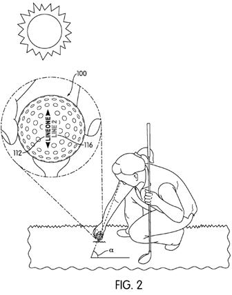
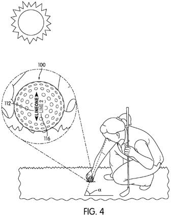
[0032] FIGS. 2-5 show examples of how the visibility and/or legibility of the separate lines of printing on golf ball 100 change as the viewing angle of the golfer changes. FIGS. 2 and 4 show golf ball 100 being viewed at a first viewing angle .alpha.. At first viewing angle .alpha., both first printed line 112 and second printed line 116 are clearly visible and/or legible. First viewing angle .alpha. may be any angle, but is in some embodiments any angle where golf ball 100 is not being viewed from the golfer’s address position or putting stance. Additionally, golf ball 100 is rotated so that the incident light is not shining directly onto first printed line 112 and second printed line 116.
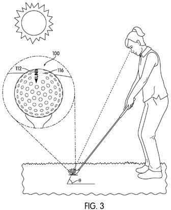
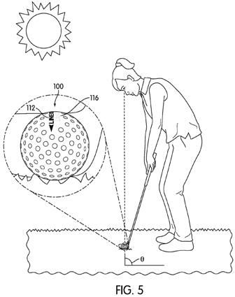
[0033] FIGS. 3 and 5 show golf ball 100 being viewed at a second viewing angle .theta., when the golfer is in the address position or in a putting stance. First viewing angle .alpha. is different from second viewing angle .theta.. Additionally, golf ball 100 is rotated so that the incident light is shining more directly onto first printed line 112 and second printed line 116. When the golfer is viewing golf ball 100 from second viewing angle .theta., second printed line 116 appears to fade or disappear.
[0034] While not being bound by any particular theory for why second printed line 116 appears to fade or disappear, the optical illusion of the fading print is likely linked to the color selection for second printed line 116 and/or the combination of the color selection of second printed line 116 and surface 118. The color may be measured or described using any method, such as CIELAB, CIE XYZ, Pantone color chips and names, or the like. A high contrast color with surface 118 will tend to be visible and stay legible at most or all angles, while a low contrast color will tend to be legible at some angles and appear to fade or disappear at other angles. For example, if golf ball 100 is white, a lighter color (a gray, metallic silver, pale yellow, pink or the like) is a low contrast color that will tend to appear to fade or disappear at certain angles. A darker color (black, dark reds, dark blues, dark greens or the like) is a high contrast color that will tend to be visible and stay legible at all or nearly all angles.
[0035] In some embodiments, for example, second printed line 116 has a color selected to be similar to the color of surface 118 of golf ball 100 while the color of first printed line 112 is a highly contrasting color to that color of surface 118. The color differential is sufficiently large so that second printed line 116 is legible and noticeable when viewed at some angles, but when the incident light hits second printed line 116 at a selected angle or group of angles, the difference in color between second printed line 116 and surface 118 is minimized so that second printed line 116 appears to blend in with the color of surface 118. Because of the high contrast between the color of first printed line 112 and the color of surface 118, first printed line remains highly visible and legible against the background of surface 118. For example, for a typically white surface 118, the color of first printed line may be black or a similarly dark hue while the color of second printed line 116 may be gray or silver.
[0036] One reason why the color of second printed line 116 appears to face into the color of surface 118 may be that the angle of the incident light may change the proportion of the diffuse and specular reflection of light from the surface of golf ball 100 or the intensity of the specular reflection component in the reflected light. In diffuse reflection, the reflected light is somewhat randomly scattered by imperfections in the surface(s) of golf ball 100. A high proportion of diffuse reflection is familiarly known as a matte surface. In specular reflection, the reflected light is reflected in a single direction. A high proportion of specular reflection is familiarly known as a glossy surface. A very high proportion of specular reflection is a mirror or mirrored surface. This altering of the proportion of diffuse and specular reflection or the intensity of the specular reflection is particularly likely if reflective particles are used in the color medium for second printed line 116 or any of the additional lines of indicia 110 or if the color medium of second printed line 116 or any covering coatings has gloss or high gloss finish.
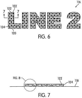
[0037] FIGS. 6-9 show how the alteration of the proportion of diffuse reflection to specular reflection could occur. FIG. 6 shows an enlarged view of second printed line 116, where each individual character 120 of second printed line 116 is formed from a plurality of reflective particles 122 suspended in a matrix or base material 124. In some embodiments, base material 124 may be clear or transparent, but in other embodiments base material 124 is provided with pigmentation so that base material 124 includes an opaque or translucent (partially opaque) color. For example, if the overall observed color of second printed line 116 appears to be silver, base material 124 may be provided with a gray color pigment. The metallic or glittery appearance is then provided by reflective particles 122, which may be silvered particles with a metallic sheen and/or high luster. Reflective particles 122 may be any type of particle known to have a metallic sheen and/or high luster to cause a high amount of reflectivity. In other embodiments, all of the observed color of second printed line 116 is provided by the reflective particles 122. For example, if second printed line 116 appears to be silver, the silvered particles with a metallic sheen and/or high luster provide the perceived color.
[0038] Reflective particles 122 may be randomly oriented within base material 124, as shown in FIG. 7. In this configuration, the highest level of shine from the particles would not necessarily occur at the same angle. As shown in FIG. 8, three different reflective particles, first particle 126, second particle 128, and third particle 130 are hit, respectively, by first incident light ray 140, second incident light ray 142, and third incident light ray 144. Each incident light ray is parallel to the other incident light rays. Because of the random orientation of the refle
ctive particles, the incident light rays encounter the particles at different incident angles: first incident light ray 140 hits first particle at first incident angle .beta. (measured from the normal line N to a particle surface); second incident light ray 142 hits second particle 128 at second incident angle .delta.; and third incident light ray 144 hits third particle 130 at third incident angle .epsilon., where each of these incident angles is different. Because the law of reflection requires that the reflected light rays are at the same angle to the normal line of the surface as the incident light rays, each particle produces reflected light rays at a slightly different angle: first particle 126 produces first reflected ray 150 at first reflected angle .gamma.; second particle 128 produces second reflected ray 152 at second reflected angle .rho.; and third particle 130 produces third reflected ray 154 at third reflected angle .eta.. These different angles are all different, which produces diffuse reflection. Also, none of the particles is producing a reflected ray that travels back on the same path as the incident light ray. Such a ray is typically considered the highest level of reflection and can often “dazzle” the eye with a bright sheen or glare.[0039] This dazzling effect is shown in FIG. 9, where the incident light hits at least one particle so that the highest level of reflection is achieved. Fourth incident ray 146 hits first particle 126 at a fourth incident angle .lamda. which generates fourth reflected ray 156 at fourth reflected angle .mu.. Fifth incident ray 147 hits second particle 128 at a fifth incident angle of 0 degrees, which generates fifth reflected ray 157 which travels directly back on the same path as fifth incident ray 147 at a fifth reflected angle of 0 degrees. Sixth incident ray 148 hits third particle 130 at a sixth incident angle .sigma., which generates sixth reflected ray 158 at a sixth incident angle .tau.. While these reflections are also at slightly different angles so as to produce diffuse reflection, reflective particles 122 may settle within base material 124 so that many of reflective particles 122 may have the highest level of shine when the incident light shines at a specific angle or relatively small range of angles, such as when the light shines directly onto second printed line 116, as shown in FIG. 9. Further, having some particles achieve an extremely high level of reflection, such as when the angle of reflection is 0 degrees or between -15 and +15 degrees, the dazzle effect of this glare may be sufficient to shift the apparent proportion of diffuse and specular reflection.
.
.
.
Example[0047] A solid golf ball is manufactured with a cover made of an ionomer resin. A white paint layer is applied to the cover. Two indicia are provided on the cover, where the indicia is provided according to an embodiment of the invention. The indicia include an alignment guide which is provided in a black color. The alignment guide comprises a partial brand name for the ball with arrow graphics at the beginning and end of the partial brand name. Additional lines of the indicia are provided in a first indicia in Cool Gray 10 (a metallic gray tone with bluish undertones), NB 9522. In a second indicia on the opposite side of the ball, the additional lines are provided in PMS 877 Silver. The ball was then coated with a clear polyurethane coating.
[0048] The finished ball was observed with the light source positioned directly overhead by holding the ball so that the first indicia was facing the observer. Both lines of printing of the first indicia were visible and legible, though the additional line of printing was observed to be somewhat difficult to read. The finished ball was then rotated so that the first indicia faced upward, so that the first indicia faced the light source while the position of the observer did not change. The alignment guide was visible while the additional line appeared to fade and was no longer legible.
[0049] The ball was again rotated so that the second indicia faced the observer with the light source positioned directly overhead. Both lines of printing of the second indicia were visible and legible. The additional line of printing was observed to the easier to read than the first indicia additional line of printing. The finished ball was then rotated so that the second indicia faced upward, so that the second indicia faced the light source. The alignment guide was visible while the additional line appeared to fade and was no longer legible.
Interesting for sure but “dazzling effects” aside, how is this going to improve my game?
David Dawsey – Keeping an Eye on Golf Ball Technology
PS – click HERE to read more interesting golf ball patent posts