
Is Your Wedge Lacking the Appropriate Traces?
What’s a trace you ask? Take a look at these figures from a Bridgestone patent application that published today and it will become clear.
Starting to see a trend? There is a lot of real estate between those grooves to capitalize on. Recall my post titled “Does Your Club Face Need Some Engineered Texturing? Taylor Made Thinks So!”
The Bridgestone patent application published today as US Pub. No. 20090176597 titled “Golf Club Head.” The application explains (keep in mind that grooves are referred to as corrugations):
[0004] U.S. Pat. No. 5,437,088 describes a golf club head in which traces (cutting marks) are formed on the face by milling (cutting by a milling machine). According to this patent, after forming corrugations (scoring lines) on the face, the face undergoes milling to sharpen the edges of the corrugations. The sharp edges and traces formed by milling increase the spin of the ball. FIG. 1a of this patent shows that the pitch of the corrugations is almost equal to that of the traces. As the traces, both downwardly convex arcuate traces and upwardly convex arcuate traces are formed. With this machining method, however, the depths and widths of the grooves may undesirably become nonuniform depending on the inclination of the face.
[0005] When forming the traces with the same pitch as the pitch (usually 2.8 mm to 3.6 mm) of the corrugations, as in U.S. Pat. No. 5,437,088, the amount of spin does not increase very much.
SUMMARY OF THE INVENTION
[0006] It is an object of the present invention to provide a golf club head that can hit a ball with a sufficiently large amount of backspin.
[0007] According to the present invention, there is provided an iron type golf club head made of metal and including a flat face, comprising: a plurality of traces formed by milling on the face, wherein the pitch of the traces is between 0.1 mm and 1 mm.
[0008] The golf club head according to the present invention comprises the plurality of traces at a small pitch. The traces themselves enhance the function of increasing the friction between the face and ball to increase the amount of backspin (to be merely referred to as amount of spin hereinafter) of the ball.
.
.
.
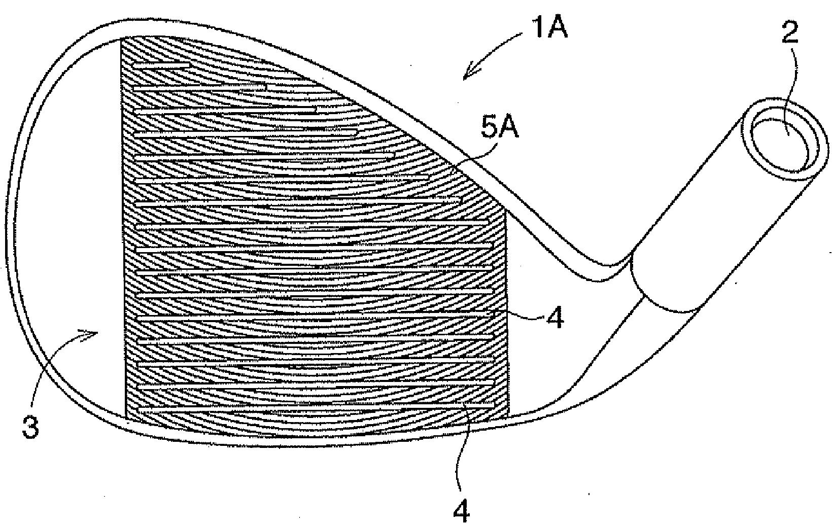
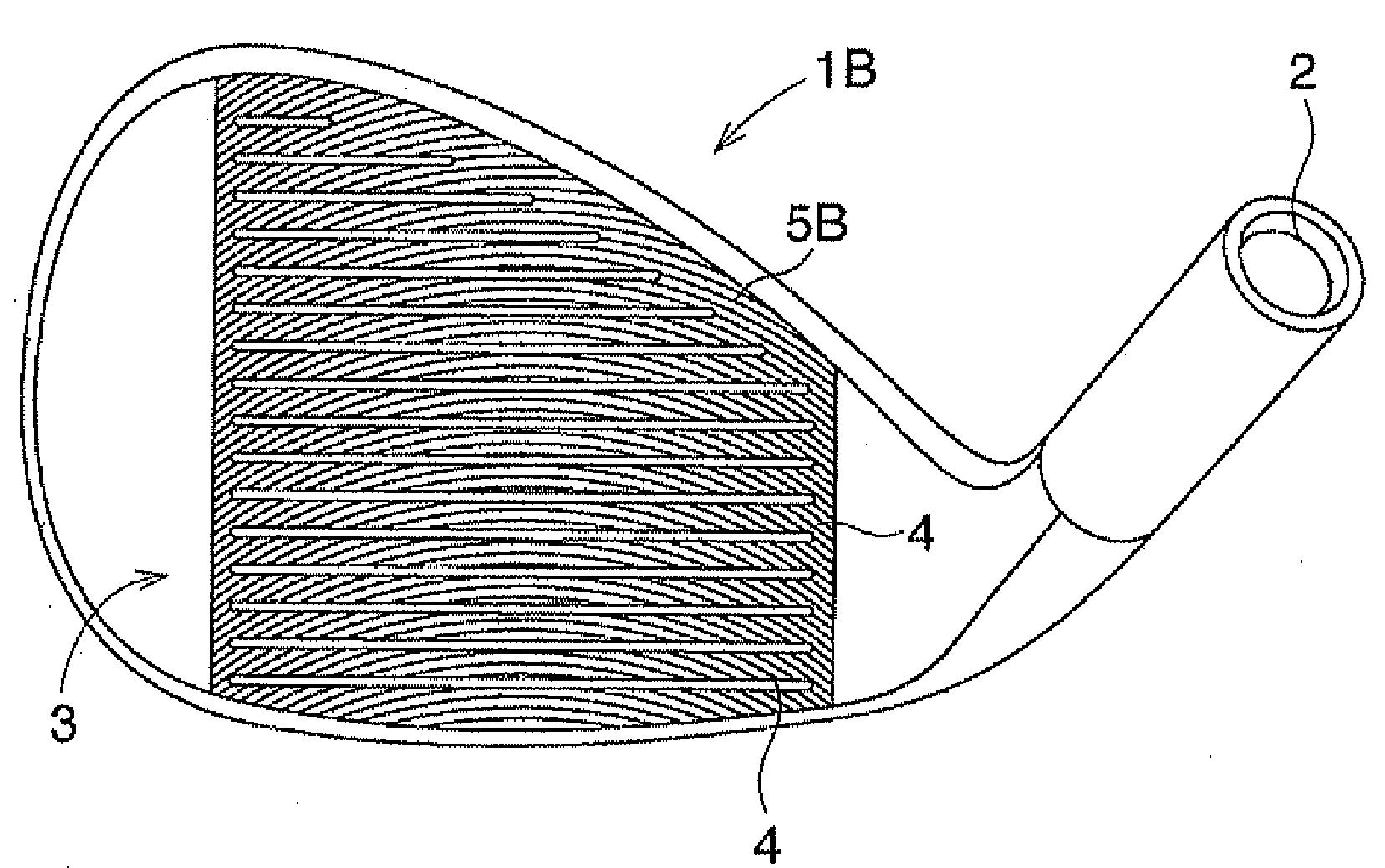
[0019] The traces 5A in FIG. 3 form downwardly convex arcs. The lowermost portion of each arc is located at the center (the center in the toe-and-heel direction) of the face. When the traces 5A form arcs in this manner, if arranging the tops of the arcs near the center of the face 3, the traces 5A can give the ball spin in the straight. The traces 5A are almost parallel to each other. More specifically, the distances among the traces 5A are almost the same in the longitudinal direction of the traces 5A. Being almost the same signifies that the error falls within a range of +-5%. If the traces 5A do not cross each other but extend parallel to each other in this manner, the friction characteristics between the ball and face 3 in the entire face 3 become uniform.[0020] The traces 5B in FIG. 4 form upwardly convex arcs. The uppermost portion of each arc is located at the center (the center in the toe-and-heel direction) of the face. When the traces 5B form arcs in this manner, if arranging the tops of the arcs near the center of the face 3, the traces 5B can give the ball spin in the straight direction. The traces 5B are almost parallel to each other (more specifically, the distances among the traces 5B are almost the same in the longitudinal direction of the traces 5. If the traces 5B do not cross each other but extend parallel to each other in this manner, the frictional characteristics between the ball and face 3 in the entire face 3 become uniform.
[0021] In the embodiments shown in FIGS. 3 and 4, the traces 5A and 5B preferably have radii of curvature of 70 mm to 150 mm, more preferably about 80 mm to 120 mm.
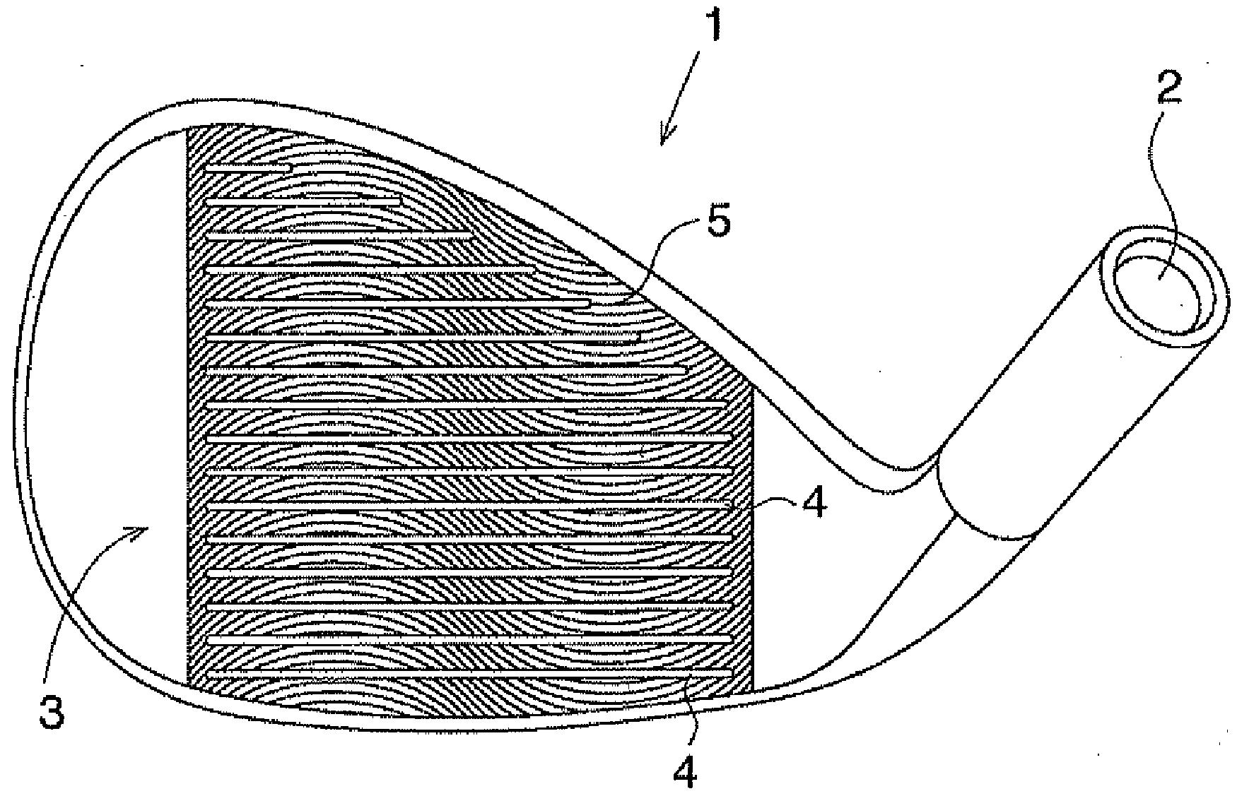
[0022] In the golf club head 1 of FIGS. 1 and 2, the traces 5 include upwardly convex arcs with a radius of curvature of about 40 mm to 80 mm on the toe side with respect to the center of the face 3, and downwardly convex arcs with a radius of curvature of about 40 mm to 80 mm on the heel side, thus forming an S shape as a whole. As shown in FIG. 1, the traces 5 are consecutive from the toe side to the heel side. The uppermost portions of the convexes and the lowermost portions of the concaves are preferably located within a range of 20 mm to 30 mm from the center. In FIGS. 1 and 2 as well, the distance between the adjacent traces 5 is almost the same in the longitudinal direction of the traces 5. If the traces 5 do not cross each other but extend parallel to each other in this manner, the frictional characteristics between the ball and face 3 in the entire face 3 become uniform.
[0023] In FIG. 1, the traces 5 are upwardly convex on the toe side and downwardly convex on the heel side. Conversely, the traces 5 may be downwardly convex on the toe side and upwardly convex on the heel side.
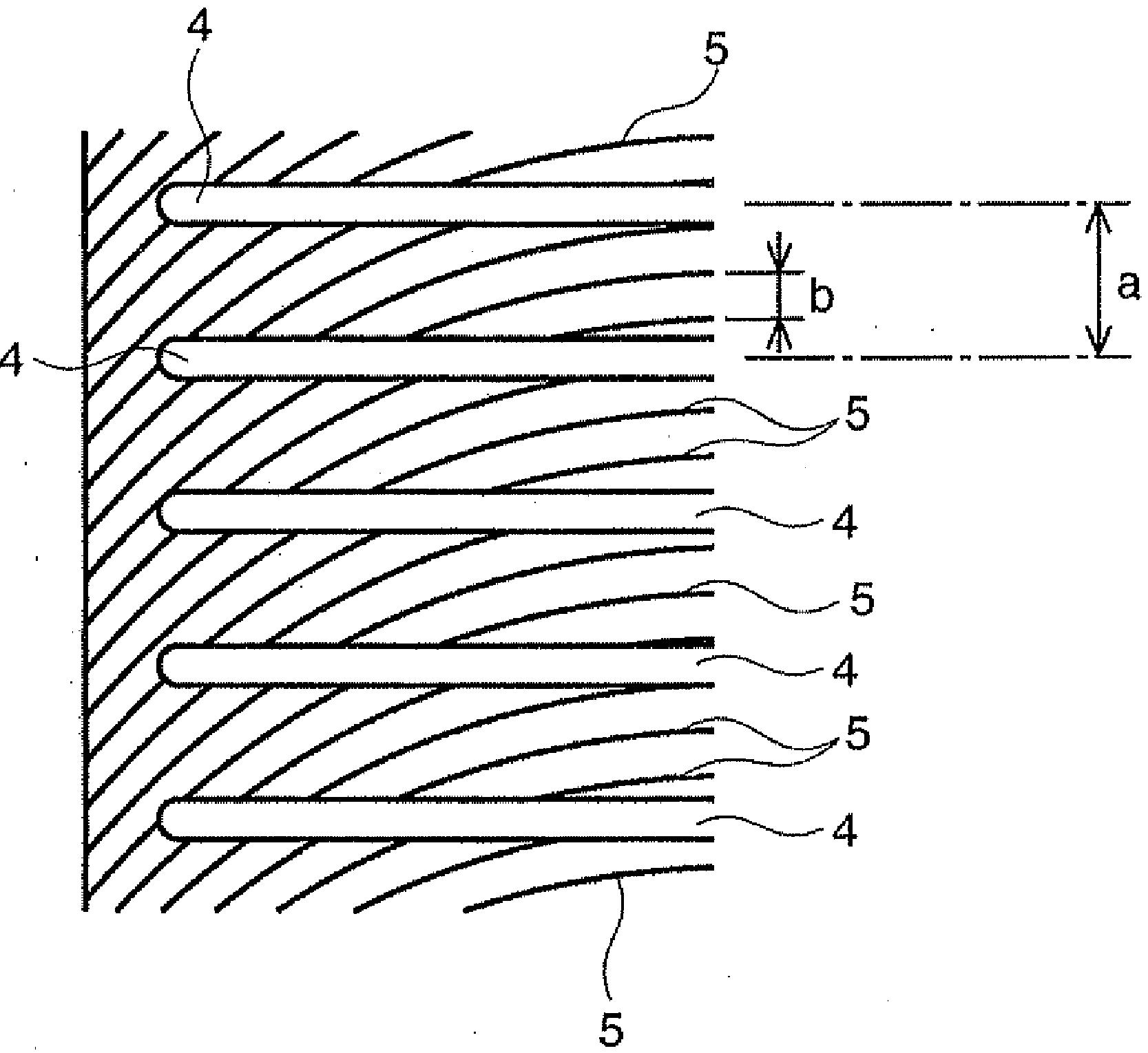
[0024] A pitch b (the distance between the adjacent two traces) of the traces 5, 5A, or 5B is between 0.1 mm and 1 mm. The pitch b is preferably between 0.1 mm and 0.5 mm.
[0025] On the surface that has undergone milling, the traces extend in the form of sharp ridge-like convex streaks, and the portions among the traces extend in the form of arcuate concave streaks. The depths of the concave streaks (the differences in height between the vertexes of the convex streaks and the deepest portions of the concave streaks) are preferably between 15 and 30 micrometers.
[0026] In the golf club heads 1, 1A, and 1B formed in this manner, as the traces 5, 5A, and 5B are dense, the amount of spin increases.
[0027] In particular, in the golf club head 1 in FIGS. 1 and 2, as the arcs form an S shape, the traces 5 extend obliquely near the center of the face. This imparts a slight frictional force having a component in a direction perpendicular to the traces 5 to the spin of the ball which is hit near the center of the faces. Therefore, the golf club head 1 in FIGS. 1 and 2 imparts very slight draw spin to the ball.
[0028] In contrast to the golf club head 1 in FIG. 1, when forming S-shaped traces including downward convexes on the toe side and upward convexes on the heel side, the golf club head 1 imparts very slight fade spin.
[0029] In the golf club head 1, the corrugations 4 may be formed on the face 3, and thereafter the face 3 may undergo milling to form the arcs 5, 5A, or 5B. Preferably, the face 3 undergoes milling first to form the arcs 5, 5A, 5B, and thereafter the corrugations 4 are formed by cutting.
[0030] In this manner, in the manufacture of the golf club head, when forming the corrugations 4 after milling, the edges of the corrugations 4 become sharp to increase the amount of spin.
[0031] Preferably, no plating film is formed on the face 3 but an oxide film is formed, and the surface hardness is set to 300 Hv, preferably 250 Hv to 180 Hv. The plating film rounds the edges of the corrugations 4 and decreases steps in the traces. Surface treatment can harden the surface, thus preventing wear.
Fascinating stuff!
Dave Dawsey
– Watching Golf Wedge Inventions
PS – check out additional wedge related inventions here, here, here, here, here, here, here, here, here, and here