
I thought it was a Cool New Nike Putter, Turns Out it is a Driver or Wood
Nike R&D must be a pretty cool place to work because it doesn’t look like they rule out any club head designs as being too radical. In fact, just check out a few recent posts on some of their interesting designs (HERE, HERE, HERE, HERE, and HERE). Well, this week I opened up a Nike patent application that had just published and thought “interesting putter.” A few seconds later I realized that the application is not directed to a putter, but rather a driver or fairway wood. Now they had my attention!
The patent application published as US Pub. No. 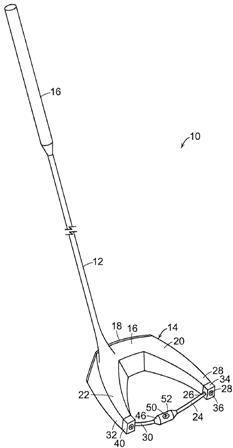

The patent application explains:
[0020] An illustrative embodiment of a golf club 10 is shown in FIG. 1 and includes a shaft 12 and a golf club head 14 attached to shaft 12. Golf club head 14 may be any driver, wood, or the like. Shaft 12 of golf club 10 may be made of various materials, such as steel, aluminum, titanium, graphite, or composite materials, as well as alloys and/or combinations thereof, including materials that are conventionally known and used in the art. Additionally, the shaft 12 may be attached to the club head 14 in any desired manner, including in conventional manners known and used in the art (e.g., via adhesives or cements at a hosel element, via fusing techniques (e.g., welding, brazing, soldering, etc.), via threads or other mechanical connectors, via friction fits, via retaining element structures, etc.). A grip or other handle element 16 is positioned on shaft 12 to provide a golfer with a slip resistant surface with which to grasp golf club shaft 12. Grip element 16 may be attached to shaft 12 in any desired manner, including in conventional manners known and used in the art (e.g., via adhesives or cements, via threads or other mechanical connectors, via fusing techniques, via friction fits, via retaining element structures, etc.).
[0021] Club head 14 includes a plurality of components. As illustrated, this example golf club head 14 includes a body member 16 and a face plate 18 positioned on a front surface of body member 16. A first arm 20 and a second arm 22, spaced from first arm 20, extend rearwardly from body member 16 defining between the arms a space 23 that extends through club head 14. In the illustrated embodiment, body member 16, first arm 20, and second arm 22 cooperate to form a substantially V-shaped club head 14.
[0022] A bar 24 has a first end 26 connected to a free end 28 of first arm 20, and a second end 30 connected to a free end 32 of second arm 22 such that bar 24 extends between first arm 20 and second arm 22. In certain embodiments, bar 24 is curved. In the embodiment illustrated in FIG. 1, bar 24 is curved outwardly away from free ends 28 and 32 of first and second arms 20, 22, respectively, in a direction extending away from body member 16 and face plate 18.
[0023] In the illustrated embodiment a first mounting member 34 is connected to first end 26 of bar 24. A first aperture 36 extends through first mounting member 34, and a fastener, such as first screw 38 extends through first aperture 36 and secures first mounting member 34 to first arm 20.
[0024] Similarly, a second mounting member 40 is connected to second end 30 of bar 24. A second aperture 42 extends through second mounting member 40, and a fastener, such as second screw 44 extends through second aperture 42 and secures second mounting member 40 to second arm 22.
[0025] In the illustrated embodiment, bar 24 has a substantially cylindrical cross-section. It is to be appreciated that bar 24 can have another cross-section such as rectangular, triangular, or any other desired cross-section. Bar 24 may be formed of various materials, such as steel, aluminum, titanium, graphite, or composite materials, as well as alloys and/or combinations thereof, including materials that are conventionally known and used in the art.
[0026] A weighted member 46 is positioned on and movable along bar 24. Weighted member 46 has a central aperture 48 extending therethrough. In the illustrated embodiment, with bar 24 having a substantially cylindrical cross-section, central aperture 48 is substantially cylindrical. It is to be appreciated that central aperture 48 would have a shape mating with that of the cross-section of bar 24.
[0027] In certain embodiments, a fastener such as a set screw 50 extends through an aperture 52 formed in weighted member 46 to secure weighted member 46 to bar 24. Thus, weighted member 46 can be moved to any desired position along bar 24 and secured in that desired position with set screw 50, or any other suitable fastener. By positioning weighted member 46 at different positions along bar 24, the performance of club head can be altered and optimized to accommodate the swing of a particular golfer, and can be changed for a particular golfer as their swing changes over time. By moving weighted member 46, the center of gravity of the club can be altered, provide a club head that is more toe-weighted or heel-weighted, as well as moving the center of gravity closer to or further away from face plate 18.
[0028] Weighted member 46 may be formed of various materials, such as steel, aluminum, titanium, graphite, or composite materials, as well as alloys and/or combinations thereof, including materials that are conventionally known and used in the art.
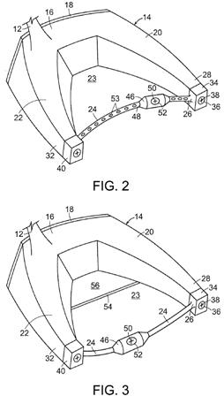
[0029] In certain embodiments, as illustrated in FIG. 2, bar 24 may be curved inwardly toward body member 16 and face plate 18. Additionally, a plurality of recesses 53 may be formed along bar 24, each of which is sized to accommodate set screw 50, thereby providing an improved registration of weighted member with respect to bar 24. Recesses 53 provide a limited number of positions at which weighted member 46 may be secured along bar 24. It is to be appreciated that other fasteners may be used to removably secure weighted member 46 to bar 24, such as pins, fasteners with a ball and mating recesses, or other detent mechanisms. Other suitable fasteners for removably securing weighted member 46 to bar 24 will become readily apparent to those skilled in the art, given the benefit of this disclosure.
[0030] In certain embodiments, as illustrated in FIG. 3, a sole plate 54 may be included in club head 14. Sole plate 54 is secured to a bottom surface of body 16 of club head 14, and extends laterally across club head 14 between first arm 20 and second arm 22. Sole plate 54 may be formed of the same material as body 16 or any other desired material.
[0031] Sole plate 54 may extend rearwardly from a front edge of club head 14 along only a portion of first arm 20 and second arm 22. In the illustrated example, sole plate 54 extends rearwardly to approximately a midpoint or central portion of each of first arm 20 and second arm 22. In such an embodiment, an upper surface 56 of sole plate 54 is exposed to an exterior of club head 14 through space 23 formed between first arm 20 and second arm 22. The remainder of space 23 rearwardly of sole plate 54 is unobstructed and provides a clear path vertically through club head 14. The inclusion of sole plate 54 provides a club head for a driver that conforms to the current requirements of the United States Golf Association.
[0032] Another embodiment is illustrated in FIG. 4 in which bar 24 is pivotable with respect to first arm 20 and second arm 22. In this embodiment, as shown by the solid lines, bar 24 can be pivoted to a point where it curves outwardly away from body 16. Bar 24 can also be pivoted, as shown in dashed lines, such that it curves inwardly toward body 16. In such an embodiment, first end 26 of bar 24 may be pivotally received in a first aperture 58 formed in first mounting member 34, and second end 30 of bar 24 may be pivotally received in a corresponding second aperture (not visible) in second mounting member 40. In other embodiments, first aperture 58 may be formed directly in free end 28 of first arm 20 and the corresponding second aperture. It is to be appreciated in certain embodiments, bar 24 may be temporarily fixed with respect to body 16 once it has been pivoted to a desired position by a detent mechanism or any other means, and other suitable means will become readily apparent to those skilled in the art, given the benefit of this disclosure. Providing bar 24 with the ability to pivot allows the center of gravity of club head 14 to be moved closer to, or further away from face plate 18.
[0033] Another embodiment is shown in FIG. 5, in which a movable indicator 60 is located on club head 14. In the illustrated embodiment indicator 60 is positioned on upper surface 56 of sole plate 54. In certain embodiments, an aperture 62 in indicator 60 receives and pivots about a pin or post 64 extending upwardly from upper surface 56 of sole plate 54. Movable indicator 60 can be pivoted by the user to a desired position to assist the user in aligning their golf shot. In the illustrated embodiment in FIG. 5 a first end 66 of indicator 60 is hemispherical in shape and contains aperture 62, with a second end 68 tapering to a point as it extends away from first end 66. It is to be appreciated that indicator 60 can be made of any desired material, and may be formed of the same material as that of body 16, or any other material.
[0034] Another embodiment is illustrated in FIG. 6 in which bar 24 extends straight between first arm 20 and second arm 22 rather than being curved between the arms. Such an embodiment allows the center of gravity of club head 14 to be moved laterally along club head 14 between a toe-weighted weighted position and a heel-weighted position, while maintaining the distance between the center of gravity and face plate 18.
[0035] Yet another embodiment is shown in FIG. 7, in which sole plate 56 extends rearwardly to the free ends 28 and 32 of first arm 20 and second arm 22, respectively. In this embodiment, bar 24 pivots with respect to first arm 20 and second arm 22, and retaining members are used to removably secure bar 24 to sole plate 56. In the illustrated example, a pair of first retaining members 70 in the form of first spring clips 70 are secured to upper surface 56 of sole plate 54, and serve to releasably receive bar 24 when bar 24 is in a forwardly rotated position, thereby releasably securing bar 24 to sole plate 54. A pair of second retaining members 72 in the form of second spring clips 72 are secured to upper surface 56 of sole plate 54, and serve to releasably receive bar 24 when bar 24 is in a rearwardly rotated position, thereby releasably securing bar 24 to sole plate 54. Releasably securing bar 24 to sole plate 54 with first and second retaining members 70, 72 may help enhance the rigidity of club head 14.
[0036] As noted above, in the illustrated embodiment a pair of first retaining members 70 and a pair of second retaining members 72 are used to releasably secure bar 24 to sole plate 54. However, it is to be appreciated that in other embodiments, a single first retaining member and single may be used to releasably secure bar 24 to sole plate 54. In yet other embodiments, more than two first retaining members and more than two second retaining members may be used to secure bar 24 to sole plate 54.
[0037] Although spring clips are illustrated here for first and second retaining members 70, 72, it is to be appreciated that any suitable retaining member may be used to releasably secure bar 24 to sole plate 54. Other suitable configurations and constructions for retaining members 70, 72 will become readily apparent to those skilled in the art, given the benefit of this disclosure.
I just wish some of these radical designs would make it to the market so we could see if they would sell. So, are you more like to game this Nike V-shaped golf club head or Callaway’s C-shaped golf club head?
Dave Dawsey – The IP Golf Guy