
Honest Officer, That Needle You Found in My Trunk is used to Adjust My Golf Club
Imagine the look you would receive if you ever uttered those words to a police officer; however, someday it may actually be true! Nike Golf recently had an interesting patent application publish as US Pub. No. One property of the viscous substance that can influence the stiffening effect of the stiffening element is the viscosity of the substance. Substances with higher viscosity have greater resistance to deformation, and thus can provide increased stiffening effect compared to substances having lower viscosity. Another property of the viscous substance that can influence the stiffening effect of the stiffening element is the compressibility of the substance. Many fluids are incompressible or nearly incompressible and may offer greater stiffening effect, while others may have a substantial degree of compressibility. Additionally, the chamber of the stiffening element may contain both viscous and gaseous substances, or a gaseous substance alone. In that configuration, the pressure of the gaseous substance, alone or in combination with the compressibility and/or viscosity of the viscous substance, may influence the stiffening effect. In another embodiment, the viscous substance may solidify after it is inserted into the chamber, such as through a phase change, chemical reaction (including polymerization reactions), etc. For example, the viscous substance may be a thermosetting material or other material that sets as a result of a chemical reaction. As another example, the viscous substance may be a thermoplastic material or other material that may be injected in liquid form and hardens upon cooling. The physical properties of such a solid, such as Young’s modulus, ductility, hardness, etc., may also influence the stiffening effect of the stiffening element. It is understood that additional properties of a substance or substances contained in the chamber may influence the stiffening effect.
.
.
.
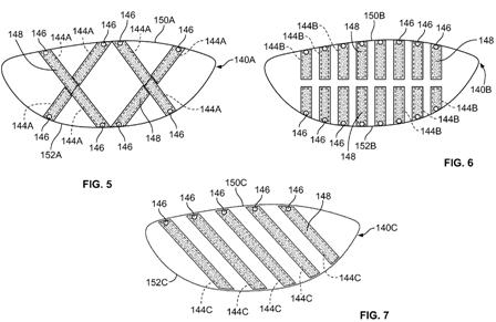

[0076] FIG. 8 illustrates a stiffening element 140D in the form of a cartridge having six chambers 144D in the form of oval cavities distributed across the cartridge 140D. The chambers 144D are positioned at the high-heel, high-center, high-toe, low-heel, low-center, and low-toe areas of the cartridge 140D. Each of the chambers 144D has a port 146 providing access to fill, empty, and refill the chambers 144D with a viscous substance 148. The ports 146 are accessible through the top and bottom edges 150D, 152D of the cartridge 140D, and the ports 146 are provided with passages 147 extending from the edges 150D, 152D of the cartridge 140D to the respective chambers 144D.
[0077] It is understood that cartridge-type stiffening elements according to other embodiments may be provided in any number of other configurations. Each different configuration may provide different options for customization of the stiffness of the face 112 of a ball striking head 102 into which the cartridge is inserted. Additionally, in another embodiment, each chamber of the stiffening element may not be provided with an individual port 146, but instead provided with a common port. For example, passages through the cartridge may connect several chambers together, such that multiple chambers can be filled through a single port 146. Further, while the chambers 144A-D of the stiffening elements 140A-D of FIGS. 5-8 are configured for filling and refilling with viscous substances, it is understood that the ports 146 may be permanently closed after filling, as described above.
[0078] In another embodiment, a ball striking head has one or more retainers on an inner surface of the face, which are adapted to hold one or more stiffening elements in contact with the inner face surface. FIGS. 9 and 10 illustrate embodiments of a face frame member 228, 328 for a ball striking head, where the inner surface 214, 314 of the face 212, 312 has one or more retainers 242, 342 adapted for holding stiffening elements 240, 340. Each stiffening element 240, 340 includes a chamber 244, 344 adapted to contain a viscous substance 248, 348 therein. The chambers 244, 344 are indicated by broken lines in FIGS. 9 and 10. The retainers 242, 342 are adapted to allow the stiffening elements 240, 340 to be connected, removed, and interchanged, as shown in FIGS. 9 and 10. The stiffening elements 240, 340 shown in FIGS. 9 and 10 are not configured to be emptied or refilled, but are configured to be interchanged with other stiffening elements containing different viscous substances in order to change the stiffening effect on the face 212, 312. In the embodiments illustrated, the retainers 242, 342 are resilient and flexible, allowing the stiffening elements 240, 340 to be snapped into the retainers 242, 342. However, it is understood that the retainers 242, 342 can be used to attach stiffening elements that have ports for emptying and refilling, as described above. In another embodiment, the retainers 242, 342 may be configured to removably connect to the stiffening elements 240, 340 in a different manner, such as a sliding connection, a threaded connection, an interference fit connection, an adhesive connection, a different type of snap fit connection, etc. As similarly described above, the stiffening elements 240, 340 may include cooperative structure to combine with the structure of the retainers 242, 342 to retain the stiffening elements 240, 340 in position, such as interlocking structures, threaded connections, etc.
[0079] In the embodiment shown in FIG. 9, the retainers 242 are positioned in the high-heel 260, high-toe 262, low-heel 264, and low-toe 266 regions of the face 112, and are oriented to allow the stiffening elements 240 to be placed in an X-shaped configuration. In the embodiment shown in FIG. 10, the retainers 342 are positioned to allow the stiffening elements 340 to be placed in a V-shaped configuration, extending from the high-heel region 360 and high-toe region 362 to the lower edge 315 of the face 312 proximate the center of the face 312. It is understood that in the embodiments of FIGS. 9 and 10, different types and configurations of stiffening elements may be connected to the retainers 242, 342, such as stiffening elements having different sizes and shapes than the stiffening elements 240, 340 illustrated. In additional embodiments, the retainers and associated stiffening elements may have other configuration and/or positioning.
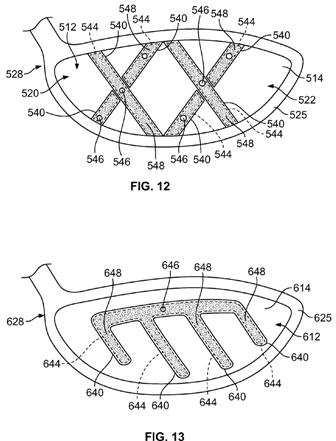
[0080] In another embodiment, the ball striking head has one or more stiffening elements permanently connected to the inner surface of the face. FIGS. 11-13 illustrate embodiments of a face frame member 428, 528, 628 for a ball striking head, where the face 412, 512, 612 has stiffening elements 440, 540, 640 permanently connected to the inner surface 414, 514, 614. In the embodiments shown, the stiffening elements 440, 540, 640 are integrally formed as part of the inner surface 414, 514, 614 of the face 412, 512, 612. In other embodiments, the stiffening elements 440, 540, 640 may be permanently connected to the face 412, 512, 612 in another manner, such as by an integral joining technique. Each stiffening element 440, 540, 640 includes a chamber 444, 544, 644 adapted to contain a viscous substance 448, 548, 648 therein. The chambers 444, 544, 644 are indicated by broken lines in FIGS. 11-13. The stiffening elements 440, 540 of the face frame members 428, 528 shown in FIGS. 11 and 12 also contain ports 446, 546 for filling, emptying, and refilling the viscous substance 448, 548 in each stiffening element 440, 540. The stiffening elements 640 of the face frame member 628 shown in FIG. 13 are interconnected, and can be filled, emptied, and refilled through a single port 646. As described above, this feature permits the stiffening effects of the stiffening elements 440, 540, 640 to be changed, by changing the substance contained in the stiffening elements 440, 540, 640.
.
.
.
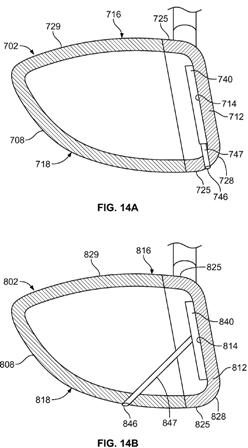
[0083] In the embodiment shown in FIG. 14A, the head 702 is formed of a face frame member 728, which includes the face 712 and walls 725 extending rearward from the face 712, and a backbody member 729 connected to the face member 728. Additionally, the head 702 has a stiffening element 740 connected to the inner surface 714 of the face 712, and a port 746 for filling, emptying, and refilling the stiffening element 740. The port 746 is accessible through one of the walls 725 of the face frame member 728, via a passage 747 extending from the wall 725 to the stiffening element 740. In the embodiment shown in FIG. 14B, the head 802 is formed of a face frame member 828, which includes the face 812 and walls 825 extending rearward from the face 812, and a backbody member 829 connected to the face member 828. Additionally, the head 802 has a stiffening element 840 connected to the inner surface 814 of the face 812, and a port 846 for filling, emptying, and refilling the stiffening element 840. The port 846 is accessible through the outer surface of the backbody member 829, via a passage 847 extending from the backbody member 829 to the stiffening element 840. The passages 747, 847 and ports 746, 846 in FIGS. 14A-B are configured for insertion of a needle (such as a hypodermic needle) to inject a viscous substance into the stiffening element 740, 840. Alternately, the passages 747, 847 may be another type of pipe, tube, conduit, or any other such structure configured for filling in another manner. In the embodiments shown in FIGS. 14A-B, the ports 746, 846 are located on the bottom side 718, 818 of the head 702, 802, which can improve the aesthetics of the head 702, 802, as well as lowering the center of gravity of the head 702, 802. In other embodiments, the head may include a port configured for accessing the stiffening element from the exterior of the head in a different manner, such as through the top side of the head, or through the face.
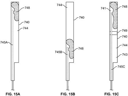
[0084] FIGS. 15A-C illustrate the stiffening member 740 of FIG. 14A being filled with a viscous substance 748 through the port 746 by a needle 745A-C. As shown in FIGS. 15A-B, needles 745A-B of varying insertion lengths can be used to fill specific areas of the chamber 744 of the stiffening member 740 with the viscous substance. For example, in FIG. 15A, a deep-inserted needle 745A is used to inject the viscous substance 748 at the top end of the chamber 744, distal from the port 746. The needle 745A can be backed up to gradually fill the chamber 744 toward the port 746, as the material will often tend to “puddle” around the injection point. As another example, in FIG. 15B, a shallow-inserted needle 745B is used to inject the viscous substance 748 at the bottom end of the chamber 744, near the port 746. The deep-inserted needle 745A and the shallow-inserted needle 745B may be different needles having different lengths, or may be the same needle inserted at different depths. It is understood that other needles with different insertion depths can be used to fill other areas of the chamber 744. Accordingly, the chamber 744 may not be completely filled with the viscous substance, and in some embodiments, if desired, a user is able to selectively fill only a specific portion of the chamber 744. Additionally, the stiffening element 740 may include one or more penetrable barriers dividing the chamber 744 into two or more separate chamber sections. Such a penetrable barrier may take the form of a membrane, a plug, a stopper, or other similar structure. The stiffening element 740 in FIG. 15C includes a penetrable barrier 749 that divides the chamber 744 into two separate chamber sections 741, 743. As also shown in FIG. 15C, a deep-inserted needle 745C can be used to penetrate the barrier 749 and inject the viscous substance 748 into the distal chamber section 741. The barrier 749 is capable of retaining the viscous substance 748 in the distal chamber section 741 and prevent leakage into the proximal chamber section 743. For example, the barrier 749 may be made from a resilient material, such as rubber or a similar material, that will expand to close the hole made by the needle 745C after removal of the needle. In a further embodiment, the chamber 744 may contain a porous material, such as a foam, netting, etc., that may assist in holding the viscous substance in place in the chamber 744.
[0085] Some embodiments of the stiffening elements described herein are generally accessible for filling, emptying, and refilling the chamber with viscous substances. As described above, the stiffening element may be accessible from the exterior of the assembled ball striking head, such as the embodiments shown in FIGS. 14A-B and 15A-C. In another embodiment, a portion of the body 108 of the head 102 can be removed in order to provide access to a stiffening element that is contained inside the head 102. As used herein, removal of any portion of the body 108 includes non-total or non-permanent removal. For example, opening a swinging or sliding door formed in the body 108 to provide access to the stiffening element constitutes removal of that portion, even though the portion is not completely removed. As another example, removal of a piece that can be reconnected later also constitutes removal.
Interesting, sure; practical, no way. In fact, I promise to buy one if such a club ever makes to onto store shelves!
David Dawsey – The Golf Patent Lawyer
PS – check out putter patents HERE