
Have You Ever Considered Energizing Your Golf Ball Via Your Tee?
Me neither! Fortunately the brains at “The Oven” are thinking about these things, as evidenced by a patent application that recently published as US Pub. No. 20110224008 titled “Golf Ball With Piezoelectric Material.” The application describes the invention as:
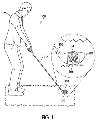
A golf ball including a piezoelectric material allows the characteristics of the golf ball to be changed by application of an electric current. An electric current may be applied to the piezoelectric material prior to impact of the golf ball by the golf club using a golf tee with a power source. An electric current may be applied to the piezoelectric material after impact of the golf ball by the golf club and during flight of the golf ball. By selectively applying or removing electric current prior to, during, or after impact with the golf club, the characteristics of the golf ball may be changed and the flight path characteristics of the golf ball may be altered.
Say what? The application goes on to explain:
.
.
.
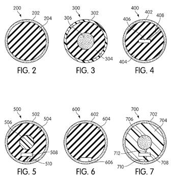
[0048] In some embodiments, piezoelectric material may be included in one or more portions of golf ball 700. In the exemplary embodiment shown in FIG. 7, piezoelectric material may comprise cover 702 and/or core 706 of golf ball 700. In some embodiments, internal circuitry 708 may selectively apply an electric current to the piezoelectric material included in one or more portions of golf ball 700, including cover 702 and/or core 706. With this arrangement, piezoelectric material in various portions of golf ball 700 may undergo compression due to the applied electric current from internal circuitry 708 at different times to affect different properties and characteristics of golf ball 700.
[0049] In some embodiments, selective application of an electric current to the piezoelectric material in golf ball 700 by internal circuitry 708 may be used before, during, and/or after golf ball 700 has been hit by a golf club to affect the club face impact and/or flight path characteristics of golf ball 700. In one exemplary embodiment, internal circuitry 708 may apply an electric current to the piezoelectric material in cover 702 via cover connecting lead 710 prior to golf ball 700 being hit with a golf club. In another exemplary embodiment, internal circuitry 708 may selectively remove the electric current to the piezoelectric material in cover 702 a predetermined amount of time after golf ball 700 has been hit by a golf club. In different embodiments, internal circuitry 708 may apply and/or remove the electric current to the piezoelectric material in cover 702 before, during, and/or after golf ball 700 has been hit by a golf club to affect the club face impact and/or flight path characteristics of golf ball 700.[0050] In another exemplary embodiment, internal circuitry 708 may apply an electric current to the piezoelectric material in core 706 via core connecting lead 712. In some embodiments, internal circuitry 708 may apply the electric current to the piezoelectric material in core 706 via core connecting lead 712. In one exemplary embodiment, internal circuitry 708 may apply and/or remove the electric current to the piezoelectric material in core 706 to affect the properties and characteristics of an impact of a club face of a golf club with golf ball 700. In different embodiments, internal circuitry 708 may apply and/or remove the electric current to the piezoelectric material in core 706 before, during, and/or after golf ball 700 has been hit by a golf club to affect the club face impact and/or flight path characteristics of golf ball 700.
[0051] In other embodiments, the electric current may be applied to one or more portions of golf ball 700 via an external apparatus. In one exemplary embodiment discussed below, an electric current may be applied to a golf ball containing piezoelectric material via a golf tee including a power source.
[0052] In the above described embodiments, piezoelectric material comprises the cover and/or the core of a golf ball. In different embodiments, piezoelectric material may comprise any layer of a golf ball, including one or more of the core, mantle, and additional core or mantle layers.[0053] In one exemplary embodiment, a golf ball may comprise a three piece configuration, including a mantle comprised of a piezoelectric material and a core and a cover comprised various natural and synthetic materials conventionally used for golf ball composition. In this embodiment, an electric current may be applied to the piezoelectric material included in the mantle of the golf ball, using the internal circuitry described above and/or external apparatus described below. With this arrangement, the piezoelectric material in the mantle of the golf ball may undergo compression due to the applied electric current to affect different properties and characteristics of golf ball. In one embodiment, the applied electric current to the piezoelectric material in the mantle of the golf ball may give the golf ball a larger apparent hardness and/or increase internal stress within the golf ball.
[0054] In other embodiments, piezoelectric material may be disposed in one or more layers of a golf ball. In some cases, piezoelectric material may be disposed between or among any combination of the core, mantle, and additional core or mantle layers. In other embodiments, piezoelectric material may be disposed on the outside of cover.
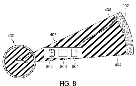
[0055] FIG. 8 illustrates an exemplary embodiment of internal circuitry within golf ball 400. As shown in FIG. 8, golf ball 400 may include internal circuitry 406. In some embodiments, internal circuitry 406 includes an energy storage device. In some cases, the energy storage device may include a battery. In other cases, the energy storage device may include a capacitor. In still other cases, the energy storage device may include any apparatus for generating an electric current. In one exemplary embodiment, internal circuitry 406 may include a battery 802 and/or a capacitor 804. Internal circuitry may use energy stored in battery 802 and/or capacitor 804 to apply an electric current to the piezoelectric material in cover 402 via connecting lead 408. In some embodiments, internal circuitry 406 may include a processor 800 for generating an electric current. Processor 800 may include a processor or other circuitry for generating electric current of any kind known in the art. In other embodiments, processor 800 may include a timer circuit for selectively applying and/or removing the el
ectric current for a predetermined period of time, upon an initiation event, or using any other criteria. In other embodiments, processor 800 may be programmed to execute various instructions and programs as is known in the art.
[0056] In other embodiments, internal circuitry 406 also may include an internal sensor for detecting the output from the piezoelectric material in cover 402 via connecting lead 408 when hit by a golf club. In some embodiments, internal circuitry 406 also may include a data storage device. A data storage device may store data from an internal sensor generated when golf ball 400 is hit by a golf club. In one embodiment, a data storage device may be used to record data associated with a golfer hitting golf ball 400 multiple times. In other embodiments, a data storage device may be used to record data associated with a golfer hitting a golf ball, such as golf ball 400, during play.[0057] FIGS. 9 and 10 illustrate views of an exemplary embodiment of a golf ball with a piezoelectric material cover arranged in a geometric pattern. Referring to FIG. 9, in this embodiment, a golf ball 900 may include a cover comprising a piezoelectric material. In some embodiments, the piezoelectric material cover may be arranged in a geometric pattern over the outer surface of golf ball 900. In one exemplary embodiment, the geometric pattern may be formed by a plurality of panels 902 comprised of the piezoelectric material. In some embodiments, a plurality of interstitial spaces 904 may be disposed between panels 902. In an exemplary embodiment, interstitial spaces 904 may be provided to allow panels 902 comprising the piezoelectric material cover to compress when subjected to an electric current. In this embodiment, interstitial spaces 904 may have a first width W1 that is associated with the distance between panels 902 in the absence of an applied electric current. In some cases, first width W1 may be associated with a first diameter D1 of golf ball 900. In different embodiments, interstitial spaces 904 may be sized and dimensioned to correspond to various widths to provide for the compression and expansion of panels 902 comprising the piezoelectric material cover of golf ball 900.
[0058] In one exemplary embodiment, panels 902 disposed over the outer surface of golf ball 900 to form the piezoelectric material cover may be arranged in a geometric pattern comprising a combination of hexagonal and pentagonal shapes. In other embodiments, panels 902 may be arranged in various patterns, including, but not limited to: hexagonal, pentagonal, triangular, circular, ovoid, elliptical, and other geometric, regular and/or irregular patterns, or combinations thereof.
[0059] Referring now to FIG. 10, in this embodiment, a golf ball 1000 is shown with a cover comprising a piezoelectric material in the presence of an applied electric field. In some embodiments, the piezoelectric material cover may be arranged in a geometric pattern over the outer surface of golf ball 1000 as described above in reference to FIG. 9. In one exemplary embodiment, the geometric pattern may be formed by a plurality of panels 1002 comprised of the piezoelectric material in a compressed state. In this embodiment, panels 1002 are compressed due to the presence of an applied electric current.
[0060] In some embodiments, interstitial spaces 1004 may be disposed between compressed panels 1002. In an exemplary embodiment, interstitial spaces 1004 may be provided to allow compressed panels 1002 comprising the piezoelectric material cover to form a substantially continuous cover when subjected to an electric current. In different embodiments, interstitial spaces 1004 may be sized and dimensioned to correspond to various widths to provide for the compression and expansion of panels 1002 comprising the piezoelectric material cover of golf ball 1000. In the embodiment of FIG. 10, interstitial spaces 1004 may have a second width W2 that is associated with the marginal distance between panels 1004 in the presence of an applied electric current. In some cases, second width W2 may be associated with a second diameter D2 of golf ball 1000. In an exemplary embodiment, second width W2 may be substantially smaller than first width W1. In one embodiment, first diameter D1 of golf ball 900 in the absence of an applied electric current may be larger than second diameter D2 of golf ball 1000 in the presence of an applied electric current. In some embodiments, first diameter D1 and/or second diameter D2 may correspond to a diameter of approximately 1.68 inches. In other embodiments, first diameter D1 and/or second diameter D2 may be greater than or less than 1.68 inches. In still other embodiments, first diameter D1 and/or second diameter D2 may be sized and dimensioned so as to conform with one or more regulations applicable to golf balls used for professional and/or amateur golf.
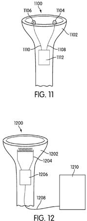
[0061] FIGS. 11 and 12 illustrate different embodiments of an external apparatus for applying an electric field to a golf ball including a piezoelectric material. Referring to FIG. 11, a golf tee 1100 may be adapted to subject a golf ball containing piezoelectric material to an electric current. In this embodiment, golf tee 1100 may include an upper surface 1102 for holding the golf ball in place.
[0062] In some embodiments, golf tee 1100 may include a first contact member 1104 and a second contact member 1106 disposed on upper surface 1102. In one embodiment, first contact member 1104 and second contact member 1106 may be provided to apply an electric current to a golf ball when placed in communication with first contact member 1104 and/or second contact member 1106 on upper surface 1102 of golf tee 1100.
[0063] In some embodiments, golf tee 1100 may include a power source 1112. In some cases, power source 1112 may be a battery and/or a capacitor. In other cases, power source 1112 may be supplied via an external power supply. In one embodiment, first contact member 1104 may correspond to a positive terminal connected to power source 1112 via a positive lead 1110. Similarly, second contact member 1106 may correspond to a negative terminal connected to power source 1112 via a negative lead 1108. In some embodiments, golf tee 1100 may use power source 1112 to apply an electric current to a piezoelectric material layer of a golf ball when the golf ball is placed in communication with first contact member 1104 and/or second contact member 1106 on upper surface 1102 of golf tee 1100. In this embodiment, the electric current applied to the golf ball in communication with first contact member 1104 and second contact member 1106 may be generated from power source 1112 via negative lead 1108 and positive lead 1110.
[0064] Referring now to FIG. 12, in this embodiment, a golf tee 1200 may be adapted to subject a golf ball containing piezoelectric material to an electric current. In some embodiments, golf tee 1200 may use an induction coil 1204 connected to a power source 1206 to generate an applied electric current. In some cases, power source 1206 may be a battery and/or a capacitor. In other cases, power source 1206 may be supplied via an external power supply. In this embodiment, golf tee 1200 may include an upper surface 1202 for holding the golf ball in place. In one exemplary embodiment, golf tee 1200 may be connected via connection 1208 to a sensor 1210 for detecting a swinging motion of a golf club. In one embodiment, sensor 1210 may incl
ude an optical detector for detecting a swinging motion of a golf club in proximity to golf tee 1200. In other embodiments, sensor 1210 may include one or more other sensors that may detect the presence of a golf club, including, but not limited to: optical, acoustical, magnetic, and other known sensors for detecting motion of a golf club.[0065] In some embodiments, golf tee 1200 and/or sensor 1210 may be in communication with a processor. The processor may be adapted to control power source 1206 to subject the piezoelectric material in a golf ball to an electric current in response to receiving a signal from sensor 1210 detecting the swinging motion of a golf club. In other embodiments, golf tee 1200 may include a pressure-sensitive contact member (not shown) to apply an electric current to a golf ball when placed in communication with the contact member on upper surface 1202 of golf tee 1200.
.
.
.
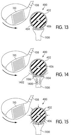
[0068] FIGS. 13-17 illustrate a series of views of an exemplary embodiment of a golf ball with a piezoelectric material being hit by a golf club 108. The order of the steps illustrated in FIGS. 13-17 is exemplary and not required. By selectively applying and/or removing an electric current to the piezoelectric material contained in a golf ball, as discussed above, the properties and characteristics of a golf ball may be changed, including, but not limited to: amount of deformation, ball speed, backspin, sidespin, total spin, and other parameters associated with a golf ball. With this arrangement, the club face impact characteristics and/or flight path characteristics of the golf ball may be altered.[0069] By applying an electric current to piezoelectric material included in a cover of a golf ball, the electric current may cause the piezoelectric material to compress, thus hardening the cover of the golf ball. With this arrangement, by selectively applying the electric current to piezoelectric material contained in a golf ball prior to impact of the golf ball by a club face of a golf club, the club face impact characteristics and/or flight path characteristics of the golf ball may be changed. In one exemplary embodiment, a ball speed and a spin rate may be affected by applying an electric current to the piezoelectric material in a golf ball prior to impact. Ball speed is the measurement of the velocity of a golf ball after impact with a club head of a golf club. Because ball speed is proportional to the force of the impact of the club head with the golf ball, the ball speed may be increased by compressing the piezoelectric material to make the cover of the golf ball harder prior to impact.
[0070] The spin of a golf ball is the rotation of a golf ball while in flight. Spin includes rotation against the direction of flight, i.e., backspin, and rotation sideways to the direction of spin, i.e., side spin. Total spin is the vector addition of backspin and side spin. The spin rate of a golf ball is the speed that the golf ball rotates on its axis while in flight. Typically, the spin rate is measured in revolutions per minute (rpm). The spin of a golf ball is related to an amount of deformation of the golf ball. The amount of deformation of the golf ball may vary based on the hardness of the golf ball, whereby a harder golf ball generally will deform less than a softer golf ball. A harder golf ball may generally achieve greater distances but have less spin. On the other hand, a softer golf ball may generally experience more spin, but will lack distance. Based on the selective application of an electric current to the piezoelectric material contained in a golf ball, the hardness may be changed, thus affecting the deformation amount and changing the spin rate of the golf ball. Similarly, in embodiments where piezoelectric material is included in a core of a golf ball, selective application of an electric current to the piezoelectric material in the core may affect a bounce back reaction after impact of the golf ball with the golf club.
[0071] In some embodiments, application of the electric current to piezoelectric material in the golf ball may change the material properties associated with the golf ball. In some cases, the electric current applied to the piezoelectric material may cause the piezoelectric material to compress. The effect of the internal stress inside the golf ball caused by the compressed piezoelectric material is similar to the effect from increasing the hardness of the golf ball. As a result, compression of the piezoelectric material in the golf ball may give the golf ball a larger apparent hardness caused by the compressed piezoelectric material.
[0072] Referring now to FIG. 13, a golf ball 400 including a cover 402 comprising piezoelectric material may be provided on a golf tee 1100 adapted to provide an electric current. In this embodiment, the piezoelectric material in cover 402 is in an uncompressed state in the absence of an applied electric current from golf tee 1100. Referring to FIG. 14, prior to impact of club face 110 of golf club 108 with golf ball 400, golf tee 1100 may use electricity 1400 from a power source to generate an electric current 1402, as discussed above. In this embodiment, golf tee 1100 applies electric current 1402 to the piezoelectric material of golf ball 400 when golf ball 400 is placed in communication with first contact member 1104 and/or second contact member 1106 on the upper surface of golf tee 1100.
[0073] Referring now to FIG. 15, electric current 1402 applied to the piezoelectric material contained in cover 402 of golf ball 400 causes the piezoelectric material to compress. As a result, cover 402 of golf ball 400 may be made harder prior to impact of club face 110 with golf ball 400. Additionally, by compressing cover 402, a diameter of golf ball 400 may be made smaller, as discussed above. As shown in FIG. 16, club face 110 of golf club 108 makes contact with golf ball 400. As club face 110 makes contact with golf ball 400, kinetic energy is transferred from club face 110 to golf ball 400. As discussed above, compression of piezoelectric material in cover 402 may cause golf ball 400 to be harder, resulting in a greater transfer of kinetic energy to golf ball 400 and, accordingly, a higher ball speed.
[0074] Referring now to FIG. 17, after impact of golf ball 400 with club face 110 of golf club 108, golf ball 400 may continue on an initial flight path. The initial flight path may be associated with the club face impact characteristics and/or flight path characteristics of the golf ball 400 when hit by golf club 108, including, but not limited to those characteristics affected by the presence or absence of an applied electric current prior to impact. In some embodiments, internal circuitry 406 may apply an electric current to the piezoelectric material in golf ball 400, as discussed above, after impact and/or during the flight of golf ball 400 on the initial flight path. In an exemplary embodiment, internal circuitry 406 may selectively apply and/or remove an electric current to the piezoelectric material in cover 402 of golf ball 400 to affect the flight path characteristics of golf ball 400. In one exemplary embodiment, internal circuitry 406 may selectively apply and/or remove the electric current to the piezoelectric material in cover 402 of golf ball 400 to alter the distance and/or loft of the initial flight path.
[0075] FIG. 18 illustrates a comparison of the club face impact characteristics and/or flig
ht characteristics of a conventional golf ball 1800 and an exemplary embodiment of a golf ball including piezoelectric material 1802 subjected to an electric current. The order of the steps illustrated in FIG. 18 is exemplary and not required. Referring to FIG. 18, a conventional golf ball 1800 may be associated with a first diameter D1. Conventional golf ball 1800 will maintain first diameter D1 when placed on a conventional golf tee at step 1810 and when hit by a golf club at step 1820. Depending on the configuration and composition of conventional golf ball 1800, it will exhibit a typical flight path 1830 that may vary depending on initial launch conditions, such as club head speed and launch angle, but will not ordinarily change once conventional golf ball 1800 is in flight.[0076] On the other hand, golf ball 1802 including piezoelectric material may be associated with a first diameter D1 in the absence of an applied electric current, as illustrated at step 1812, and may be associated with a second diameter D2 in the presence of an applied electric current, as illustrated at step 1822. With this arrangement, the properties and characteristics of golf ball including piezoelectric material 1802 may be changed prior to impact with a golf club, as shown at step 1814, by application of an electric current. In different embodiments, the electric current may be supplied by a golf tee and/or internal circuitry inside golf ball 1802, as discussed in the embodiments above.
[0077] In this embodiment, the applied electric current to the piezoelectric material may cause the cover of golf ball 1802 to compress prior to impact with the club face of a golf club, thereby causing golf ball 1802 to have second diameter D2 that is smaller than first diameter D1 associated with golf ball 1802 in the absence of the electric current. With this arrangement, the diameter of golf ball 1802 may be changed by selective application of the electric current to the piezoelectric material in the cover. In one exemplary embodiment, internal circuitry may remove the applied electric current at step 1834 to cause the diameter of golf ball 1802 to increase from second diameter D2 to first diameter D1 while golf ball 1802 is in flight. The larger relative diameter of first diameter D1 at step 1832 may increase the air resistance of golf ball 1802, thereby increasing loft of golf ball 1802 along its flight path.
[0078] FIG. 19 illustrates a comparison of the flight paths of conventional golf ball 1800 and golf ball 1802 including piezoelectric material subjected to an electric current according to the methods described herein. As shown in FIG. 19, conventional golf ball 1800 may have a conventional flight path terminating at end point 1910. The conventional flight path of golf ball 1800 may be associated with a first distance L1 to end point 1910 and also may be associated with a loft corresponding to a first height H1. In contrast, golf ball 1802 including piezoelectric material subjected to an electric current according to the methods described herein for changing the flight path characteristics may have an exemplary flight path terminating at end point 1912. In this embodiment, exemplary flight path of golf ball 1802 may be associated with a second distance L2 to end point 1912 and also may be associated with a loft corresponding to a second height H2.
[0079] In some embodiments, by using the systems and methods described herein to apply and/or remove an electric current to piezoelectric material in a golf ball, parameters associated with a flight path of golf ball may be changed or altered. In an exemplary embodiment, by applying an electric current to the piezoelectric material included in golf ball 1802 as described herein, second distance L2 may be greater than first distance L1 associated with conventional golf ball 1800. Similarly, in another exemplary embodiment, by selectively applying and/or removing an electric current to the piezoelectric material included in golf ball 1802 as described herein, second height H2 associated with the loft of golf ball 1802 may be greater than first height H1 associated with the loft of conventional golf ball 1800.
.
.
.
Now that sounds like an expensive golf ball and tee combination! Frankly, I would prefer if my ball just transformed into the shape of a remote control airplane upon impact.
David Dawsey – Keeping an Eye on Golf Ball Technology