
Golf Equipment Purists Cover Your Eyes
What is a golf equipment “purist” now days anyway? In 1990 it was someone that would never dream of hitting a metal wood, today they are. In the early 2000’s it was someone that would never dream of hitting a 460 cc driver, today they are. Then it was square heads, and so on, and so on, … Attitudes change when technology leaves you behind (or someone on Tour puts a club in play).
I say this to prepare you for the following club head design. Think about it a little bit and read what the application has to say about the technology before you race to post “I just puked in my mouth” on one of the golf forums. OK, are you prepared?
The drawings come from a Nike Golf patent application that published this week as US Pub. No. A golf club head includes a body member having a ball striking face, a crown, a toe, a heel, a sole, a rear, and a hosel region. The heel includes an airfoil-like surface shaped like the leading edge of an airfoil that extends over a majority of the length of the heel. The back may include a Kammback feature having a concavity extending from the heel-side to the toe-side of the back. The heel-side edge of the concavity may be shaped like the leading edge of an airfoil. Further, the sole may include a diffuser that extends at an angle of from approximately 10 degrees to approximately 80 degrees from a moment-of-impact trajectory direction. A hosel fairing that extends from the hosel region toward the toe may also be provided on the crown. A golf club including the golf club head is also disclosed.
The application goes on to explain:
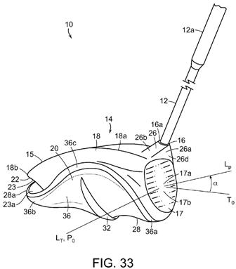
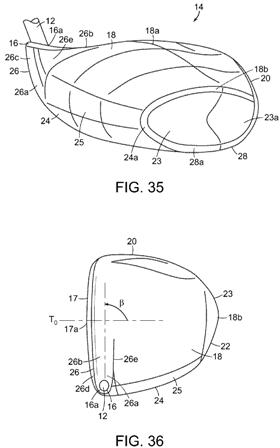
[0221] A golf club 10 according to further aspects is shown in FIGS. 33-37. In the example structure of FIG. 33, the club head 14 includes a body member 15 to which the shaft 12 is attached at a hosel or socket 16 in known fashion. The body member 15 further includes a plurality of portions, regions, or surfaces. This example body member 15 includes a ball striking face 17, a crown 18, a toe 20, a back 22, a heel 24 (e.g., see FIG. 36), a hosel region 26 and a sole 28.
[0222] As previously discussed in detail and as also shown in FIG. 35, club head 14 may include a heel 24 having a surface 25 that is generally shaped as the leading surface of an airfoil, i.e., an airfoil-like surface 25. In one example structure, as shown in FIG. 35, the height of the heel 24 (i.e., the dimension extending in the direction from the sole 28 to the crown 18 and measured from where the tangents to the surface are 45 degrees from the horizontal) is greatest closest to the hosel region 26 and least closest to the back 22. Further, in this example structure, the height of the heel 24 gradually and smoothly tapers down as the heel 24 extends away from the hosel region 26 towards the back 22.
[0223] Thus, as can be seen from FIG. 35, for the specific airfoil-like surface 25 illustrated, there are no abrupt changes in surface geometry in the heel 24. Thus, for this embodiment, the entire heel 24 is formed as a single smoothly curved surface, both as the surface 25 extends from the sole 28 to the crown 18 and as the surface 25 extends from the hosel region 26 to the back 22.
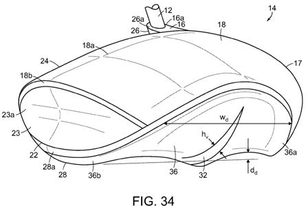
[0224] As best shown in FIGS. 34 and 35, the crown 18 may extend across the width of the club head 14, from the heel 24 to the toe 20, with a generally convex, gradual, widthwise curvature. Further, club head surface may extend smoothly and uninterruptedly from the airfoil-like surface 25 of the heel 24 into a central region of the crown 18. The crown’s generally convex, widthwise, curvature may transition from a positive to a negative curvature in the middle portion of the crown’s width. Referring back to FIG. 33, the apex 18a of the crown 18 may be approximately vertically aligned with the desired point of contact 17a in the T.sub.0 direction, when the club 10 is oriented at its 60 degree lie angle positions. Adjacent to the toe 20 of the club head 14, the crown 18 may be provided with a slight upward flaring as shown in FIGS. 33, 34 and 35. Alternatively (not shown), the crown 18 may be provided with a convex curvature across its entire width, from the heel 24 to the toe 20.
[0225] Further, the crown 18 may extend across the length of the club head 14, from the ball striking face 17 to the back 22, with a generally convex smooth curvature. This generally convex curvature may extend from adjacent the ball striking surface 17 to the back 22 without transitioning from a positive to a negative curvature. In other words, as shown in FIGS. 33, 34 and 35, the crown 18 may be provided with a convex curvature along its entire length from the ball striking face 17 to the back 22. Optionally (not shown), adjacent to the back 22 of the club head 14, the crown 18 may be provided with a slight upward flaring.
[0226] According to another aspect, the club head 14 may include an additional drag-reducing structure. In particular, the hosel region 26 may include a hosel fairing 26a that provides a transition from the hosel 16 to the crown 18. The hosel fairing 26a may assist in maintaining a smooth laminar airflow over the crown 18. In accord with the example structure of FIGS. 33, 35 and 36, the hosel fairing 26a may be relatively long and narrow and may extend onto the crown 18. The lengthwise extension of such a relatively long and narrow hosel fairing 26a may be oriented at a counterclockwise angle .beta. from the T.sub.0 direction. By way of non-limiting example, angle .beta. may range from approximately 20.degree. to approximately 90.degree.. According to other embodiments, the angle .beta. may range from approximately 30.degree. to approximately 85.degree., from approximately 35.degree. to approximately 80.degree., from approximately 45.degree. to approximately 75.degree., or even from approximately 50.degree. to approximately 70.degree..
[0227] As shown in FIGS. 33 and 35, the hosel region 26 may include a hosel fairing 26a that is generally aligned with direction P.sub.0. When the hosel fairing 26a forms a tapered transition from the hosel 16 to the crown 18 that extends generally in the P.sub.0 direction, air flowing around the shaft 12 in the P.sub.0 direction may be less likely to separate from the hosel region 26 and/or the crown 18 of the club head 14.
[0228] Referring to FIGS. 33, 35 and 36, the hosel fairing 26a is shown as having an upper surface 26b that may include an opening 16a for insertion of the shaft 12. Optionally, a hosel (not shown) may be provided for attachment of the shaft 12 to the club head 14. Upper sur
face 26b is shown extending from the opening 16a toward the toe 20 and tangentially merging with the crown 18 at or near the apex 18a of the crown 18 and adjacent to the ball striking face 17. Even further, upper surface 26b is shown as having a very slight concave curvature in the P.sub.0 direction and an essentially flat curvature in the T.sub.0 direction. Upper surface 26b have a maximum front-to-back width ranging from approximately 6 mm to approximately 12 mm. As the upper surface 26b extends from the shaft attachment region to where it merges with the crown 18, the width of the upper surface 26b may increase (i.e., the hosel fairing 26a may flare) or the width of the upper surface 26b may decrease (i.e., the hosel fairing 26a may narrow) or the width of the upper surface 26b may remain substantially constant (as shown in FIGS. 33 and 36).[0229] As best shown in FIG. 35, the hosel region 26 may also include a heel-side surface 26c located to the heel-side of the shaft 12. The heel-side surface 26c extends downward from the upper surface 26b and tangentially merges with the quasi-parabolic, airfoil-like surface 25 that forms the heel 24. In the embodiment of FIG. 35, the heel-side surface 26c is a generally convex surface that tangentially merges with the heel 24 close to the apex point of the quasi-parabolic curve. Alternatively (not shown), the heel-side surface 26c of the hosel region 26 may merge with the heel 24 above or below the apex point of the quasi-parabolic curve.
[0230] As best shown in FIG. 33, the hosel fairing 26a may include a front surface 26d that provides a smooth transition from the hosel 16 to the ball striking face 17. In this particular embodiment, the hosel region’s front surface 26d may be substantially planar. Further, the front surface 26d may be flush with the ball striking face 17. Alternatively, front surface 26d may be slightly convex or concave in at least one direction. For example, front surface 26d of the hosel fairing 26a may have a slightly concave curvature as it extends from the upper surface 26b to merge into the ball striking face 17, but may follow the same slightly convex curvature of the ball striking face 17 in the heel-to-toe direction.
[0231] As best shown in FIGS. 35 and 36, the hosel fairing 26a may also include a rear surface 26e that provides a further transition from the hosel 16 to the crown 18. The hosel region’s rear surface 26e may be substantially aligned with or parallel to the front surface 26d. Thus, both the front surface 26d and the rear surface 26e of the hosel fairing 26 may be substantially aligned with air flowing over the club head 14 in the P.sub.0 direction. Given this particular configuration, the hosel fairing 26a may present a relative narrow profile for air flowing in the P.sub.0 direction. When the rear surface 26e is substantially aligned with the front surface 26d of the hosel fairing 26 and when the heel 24 is formed with an airfoil-like surface 25, the intersection of the rear surface 26e with the heel 24 may be formed with a relatively abrupt, almost right-angle transition. Alternatively, a less abrupt, more radiused transition from the rear surface 26e to the heel 24 may be provided. Similar to the front surface 26d, the rear surface 26e may be substantially planar, slightly convex or slightly concave in one or both planar directions.
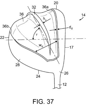
[0232] According to certain aspects and referring to FIGS. 33, 34 and 37, the sole 28 may include a diffuser 36. Referring to FIG. 37, the diffuser 36 may extend from adjacent the hosel region 26 toward the toe 20, toward the intersection of the toe 20 with the back 22 and/or toward the back 22. The diffuser 36 includes sides 36a and 36b. Optionally, the diffuser 36 may include one or more vanes 32. The cross-sectional area of the diffuser 36 gradually increases as the diffuser 36 extends away from the hosel region 26. It is expected than any adverse pressure gradient building up in an air stream flowing from the hosel region 26 toward the toe 20 and/or toward the back 22 will be mitigated by the increase in cross-sectional area of the diffuser 36. Thus, as discussed above, it is expected that any transition from the laminar flow regime to the turbulent flow regime of the air flowing over the sole 28 may be delayed or even eliminated altogether. In certain configurations, the sole 28 may include multiple side-by-side diffusers.
[0233] The one or more diffusers 36 may be oriented to mitigate drag during at least some portion of the downswing stroke, particularly as the club head 14 rotates around the yaw axis. Thus, in certain configurations and referring to FIG. 37, the diffuser 36 may be oriented at an angle .gamma. to diffuse the air flow when the hosel region 26 and/or the heel 24 lead the swing. The orientation of the diffuser 36 may be determined by finding a centerline between the sides 36a, 36b of the diffuser 36, and in the case of a curved centerline, using a least-squares fit to determine a corresponding straight line for purposes of determining the orientation. In the configuration of FIG. 37, the diffuser 36 is oriented at an angle of approximately 60.degree. from a direction parallel to the moment-of-impact club-head trajectory direction T.sub.0. The diffuser 36 may be oriented at angles that range from approximately 10.degree. to approximately 80.degree. from the T.sub.0 direction. Optionally, the diffuser 36 may be oriented at angles that range from approximately 20.degree. to approximately 70.degree., or from approximately 30.degree. to approximately 70.degree., or from approximately 40.degree. to approximately 70.degree., or even from approximately 45.degree. to approximately 65.degree. from the T.sub.0 direction. In certain configurations, the diffuser 36 may extend from the hosel region 26 toward the toe 20 and/or toward the back 22. In other configurations, the diffuser 36 may extend from the heel 24 toward the toe 20 and/or the back 22.
[0234] According to certain example configurations, the side 36a may extend at approximately 60.degree. to approximately 100.degree. from the T.sub.0 direction. As best shown in FIG. 37, the side 36a may extend at approximately 80.degree. to approximately 90.degree. from the T.sub.0 direction. The side 36b may generally extend toward the toe 20, toward the intersection of the toe 20 with the back 22, and/or toward the back 22 as the diffuser 36 extends away from the hosel region 26. According to certain example configurations, the side 36b may extend at approximately 10.degree. to approximately 70.degree. from the T.sub.0 direction. Referring to the example structure of FIG. 37, the side 36b may extend at approximately 30.degree. from the T.sub.0 direction.
[0235] Further, one or both of the sides 36a, 36b of the diffuser 36 may be curved. In the particular embodiment of FIG. 37, the side 36a is substantially straight in the embodiment of FIG. 37, while the side 36b is gently curved. As shown in FIG. 37, the side 36b may be complexly curved–convexly curved closest to the heel 24 and concavely curved closest to the toe 20. This curvature of side 36b of the diffuser 36 may enhance the diffuser’s ability to delay the transition of the airflow from laminar to turbulent over a greater yaw angle range. In other configurations, both sides 36a, 36b of the diffuser 36 may be straight. Optionally, both sides 36a, 36b may curve away from the center of the diffuser 36, su
ch that diffuser 36 flares as it extends away from the hosel region 26.[0236] As best shown in FIGS. 33 and 37, the diffuser 36 has a depth d.sub.d and a width w.sub.d. In certain configurations, the depth d.sub.d of the diffuser 36 may be constant. For example, the depth d.sub.d of the diffuser 36 may remain approximately constant, while the width w.sub.d of the diffuser 36, as measured from side 36a to side 36b of the diffuser 36, may gradually increase as the diffuser 30 extends away from the hosel region 26. Optionally, in certain configurations, the depth d.sub.d of the diffuser 36 may vary. For example, the depth d.sub.d may linearly increase as the diffuser 36 extends away from the hosel region 26. As another example, the depth d.sub.d may non-linearly and gradually increase (or decrease) as the diffuser 36 extends away from the hosel region 26. As even another example, the depth d.sub.d may have step increments as the diffuser 36 extends away from the hosel region 26. Optionally, within each step increment, the depth d.sub.d may vary.
[0237] The width w.sub.d of the diffuser 36 may be measured from the side 36a to the side 36b along a perpendicular to the centerline of the diffuser 36. Although it is expected that the width w.sub.d of the diffuser 36 will generally increase as the distance from the hosel region 26 increases, in certain configurations (not shown), the width w.sub.d of the diffuser 36 may be constant.
[0238] Further, as shown in FIG. 37, the depth d.sub.d of diffuser 36 along the length of side 36a, as the side 36a extends across the sole 28, is essentially constant. In contrast, for this particular example configuration, the depth d.sub.d of diffuser 36 along the length of side 36b across the sole 28 decreases as the distance from the hosel region 26 increases. By way of non-limiting example, in this particular embodiment, the depth d.sub.d of the diffuser 36 at side 36b as it approaches the back 22 has essentially been decreased to zero.
[0239] Even further and again referring to FIGS. 33 and 37, the depth d.sub.d of the diffuser 36 need not be constant along the width w.sub.d of the diffuser 36. For example, the depth d.sub.d may be greatest in a central region of the diffuser 36 and less in a region of the diffuser 36 that is adjacent one or more of the sides 36a, 36b. Alternatively, the depth d.sub.d across the width of the diffuser 36 may increase as the distance from the side 36a increases, may then decrease somewhat in the central region of the diffuser 36, may then increase as the distance from the central region increases, and may then decrease as the side 36b is approached.
[0240] Referring back to FIG. 34, the depth d.sub.d of the diffuser 36 may be measured from an imaginary sole surface that extends from the portion of the sole 28 adjacent to the side 36a of the diffuser 36 to the portion of the sole adjacent to the side 36b. The depth d.sub.d of any one diffuser 36 may range from approximately 0.0 mm at its minimum to approximately 10 mm at its maximum. The maximum depth d.sub.d of the diffusers 36 may range from approximately 2 mm for a relatively shallow diffuser to approximately 10 mm for a relatively deep diffuser.
[0241] Optionally, as shown in FIGS. 33, 34 and 37, the diffuser 36 may include a vane 32 in the central region of the diffuser. The vane 32 may be located approximately centered between the sides 36a and 36b of the diffuser 36 and may extend from the hosel region 26 to the toe 20. In the example structure of FIGS. 33, 34 and 37, the vane 32, which projects from the bottom surface of the diffuser 36, tapers at either end in order to smoothly and gradually merge with the bottom surface of the diffuser 36. The vane 32 may have a maximum height h.sub.v (measured from the maximum depth d.sub.d of the diffuser 36) equal to or less than the depth d.sub.d of the diffuser 36, such that the vane 32 does not extend beyond a base surface of the sole 28. The maximum height b.sub.v of vanes 32 provided on diffusers 36 may range from approximately 3 mm to approximately 10 mm. In certain configurations (not shown), the diffuser 36 may include multiple vanes. In other configurations, the diffuser 36 need not include any vane. Even further, the vane 32 may extend only partially along the length of the diffuser 36.
[0242] As can best be seen in FIGS. 33 and 34, the diffuser 36 may extend from the sole 28 into the toe 20. Even further, the diffuser 36 may extend all the way up to the crown 18. In certain configurations, as the diffuser 36 extends up along the toe 20 upward toward the crown 18, the depth d.sub.d and or the width w.sub.d of the diffuser 36 may gradually decrease. In particular configuration shown in FIGS. 33-37, the diffuser 36 includes a toe-side edge 36c that smoothly curves from the sole 28 adjacent to the ball striking face 17 up to the crown 18 and then back down to the sole adjacent to the back 22. In this example structure, the vane 32 is also shown as extending into the toe 20 and up toward the crown 18.
[0243] As best shown in FIGS. 33 and 35, the back 22 of the club head 14 may include a “Kammback” feature 23. The Kammback feature 23 extends from the crown 18 to the sole 28 and from the heel 24 to the toe 20. For this particular configuration, the Kammback feature 23 is generally confined to the back 22 of the club head 14 and does not extend across the heel 24 or across the toe 20. As discussed above, a Kammback feature 23 is designed to take into account that a laminar flow, which could be maintained with a very long gradually tapering downstream end, cannot be maintained with a shorter tapered downstream end. When a downstream tapered end is too short to maintain a laminar flow, drag due to turbulence may start to become significant after the downstream end of a club head’s cross-sectional area is reduced to approximately fifty percent of the club head’s maximum cross section. This drag may be mitigated by shearing off or removing the too-short tapered downstream end of the club head, rather than maintaining the too-short tapered end. It is this relatively abrupt cut off of the tapered end that is referred to as the Kammback feature 23.
[0244] For this particular embodiment, the Kammback feature 23 is expected to have its maximum effect on the aerodynamic properties of the club head 14 when the ball striking face 17 is leading the swing. In other words, during the last approximately 20.degree. of the golfer’s downswing prior to impact with the golf ball, as the ball striking face 17 begins to lead the swing, the back 22 of the club head 14 becomes aligned with the downstream direction of the airflow. Thus, as the Kammback feature in this particular embodiment is located on the back 22 of the club head 14, the Kammback feature 23 is expected to reduce turbulent flow, and therefore reduce drag due to turbulence, most significantly during the last approximately 20.degree. of the golfer’s downswing.
[0245] According to certain aspects, the top and bottom edges of the Kammback feature 23 may have curved profiles. In other words, when viewed from above when the club 10 is in the 60 degree lie angle position, as bes
t shown in FIG. 36, the rear edge 18b of the crown 18 is curved. In this particular example, the rear edge 18b of the crown is convexly curved. As best shown in FIG. 34, the rear edge 28a of the sole 28 may be similarly convexly curved. The curvatures of the rear edges 18b, 28a need not be the same. Further, one of the rear edges may extend beyond the other. Thus, for example, the rear edge 28a of the sole 28 may extend further back than the rear edge 18b of the crown 18. Alternatively, the curvatures of the rear edges 18b, 28a may be substantially the same, and further, the profiles of the upper and lower rear edges may be evenly aligned with each other when viewed from above. According to other embodiments, the profiles of the rear edges of the crown or the sole may be straight across, a series of linear segments, concavely curved and/or complexly curved.[0246] According to certain other aspects, the Kammback feature 23 may be provided with a concavity 23a. In the particular configuration of FIGS. 34 and 35, the back 22 may include a Kammback feature 23 having a concavity 23a extending from the heel-side to the toe-side of the back 22. Further, the Kammback’s concavity 23a may extend from the crown 18 to the sole 28 and from the heel 24 to the toe 20. Even further, the concavity 23a of the Kammback feature 23 may be bounded by a rearmost edge 18b of the crown 18, a rearmost edge 24a of the heel 24, and a rearmost edge 28a of the sole 28. In the particular embodiment of FIGS. 34 and 35, the concavity 23a curves back under or undercuts the crown 18, rather than extending straight down. Similarly, the concavity 23a also undercuts the sole 28. Even further, in this example structure, the concavity 23a also undercuts the heel 24 and the toe 20.
[0247] Further, in the example structure of FIGS. 34 and 35, the Kammback feature 23, when viewed from the back 22 of the club head 14, may have a generally air-foil like shape. For example, the heel-side of the Kammback feature 23 may be provided with a smoothly curved heel edge 24a that follows the airfoil-like shape of the heel 24, whereas the toe-side of the Kammback feature 23 may be provided with a sharper, tapered toe edge 20a formed by crown edge 18b and the sole edge 28a meeting at an acute angle. Kammback feature 23 is not limited to this specific shape. Optionally, the shape of the Kammback feature 23 may include, by way of non-limiting examples, a generally round shape, a generally elliptical shape, a generally flattened oval shape, a generally pointed oval shape, a generally egg-shape, a generally cigar shape or a generally rectangular shape. The Kammback feature 23 may have a symmetric and/or non-symmetric shape.
[0248] Even further, the bottom surface of the concavity 23a, as it extends from the heel 24 to the toe 20, is relatively flat. However, due to the convexly-curved profiles of the rear edges 18b and 28a of the crown 18 and of the sole 28, respectively, the Kammback 23 is deeper in its central region than at its ends which are adjacent to the heel 24 and to the toe 20.
[0249] In the embodiment of FIGS. 33-37, drag-reducing structures, such as the airfoil-like surface 25 of the heel 24, diffuser 36, the hosel fairing 26a, and/or the Kammback feature 23, are provided on the club head 14 in order to reduce the drag on the club head during a user’s golf swing from the end of a user’s backswing throughout the downswing to the ball impact location. Specifically, the airfoil-like surface 25 of the heel 24, the diffuser 36, and the hosel fairing 26a are provided to reduce the drag on the club head 14 primarily when the heel 24 and/or the hosel region 26 of the club head 14 are generally leading the swing. In this particular embodiment, the Kammback feature 23 is provided to reduce the drag on the club head 14 primarily when the ball striking face 17 is generally leading the swing.
Did you ever think a driver would have a diffuser, a vane, and a Kammback feature?
Sure, it isn’t much on the eyes but if it reliably provided the longest drive of the group in the fairway then I would game it.
Dave Dawsey – The Golf Attorney