
Does Your Swing Need a Contoured Backstop?
No, not a swing training device; it appears that Nike Golf has been working on a golf club head with a contoured backstop.
Backstops to control the maximum face deflection are nothing new, but they are generally flat and a fixed distance behind the face. See what you think of what the Nike engineers have disclosed in a patent application that recently published as US Pub. No. Golf club and golf club head structures include an inner wall or backstop arranged behind a ball striking surface of the golf club head and defining a gap between the inner wall and a rear surface of the ball striking surface. In some arrangements, the size of the gap may vary along a heel-to-toe length of the inner wall or backstop. For instance, the size of the gap may gradually increase from a first end of the inner wall toward a central region of the inner wall, and may gradually decrease from the central region toward a second end of the inner wall. In some examples, the inner wall or backstop may be connected to the golf club head, for instance, at a first end and/or a second end.
The application goes on to explain:
[0006] Because golf clubs typically are designed to contact the ball at or around the center of the face, off-center hits may result in less energy being transferred to the ball, thereby decreasing the distance of the shot. The energy or velocity transferred to the ball by a golf club also may be related, at least in part, to the flexibility of the club face at the point of contact, and can be expressed using a measurement called coefficient of restitution (“COR”). The maximum COR for golf club heads is currently limited by the United States Golf Association (“USGA”) at 0.83. Accordingly, it would be advantageous to provide a golf club head having a flexible ball striking surface that provides an improved or maximized COR.
.
.
.
[0008] Aspects of this invention relate to golf club and golf club head structures having a thin walled ball striking surface and a backstop arranged behind the ball striking surface on an interior of the golf club head. In some examples, the backstop may be contoured to provide a greater distance between the ball striking surface and the backstop in a central region of the backstop and ball striking surface than in an end region of the backstop and ball striking surface. This increased distance near a central region allows for additional flexing of the ball striking surface in the central region than nearer the end regions, while reducing and/or preventing overflexing of the ball striking surface. For instance, the backstop may act as a physical barrier to prevent or reduce the flex of the ball striking surface as a golf ball is struck.
.
.
.
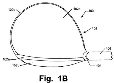
[0027] FIGS. 1A and 1B generally illustrate an example wood-type golf club 100 and/or golf club head 102 in accordance with this invention. As mentioned above, aspects of the contoured inner wall or backstop described herein may be used with various other types of golf clubs and golf club head structures, including hybrid type clubs, iron-type clubs, and the like. Although the general description of golf club structures found in FIGS. 1A and 1B is generally directed to wood-type golf club heads, nothing in the disclosure should be viewed as limiting use of the contoured inner wall or backstop as described herein to use with only wood-type golf clubs. Instead, the golf club, golf club heads, etc. described herein may be used with various types of golf clubs without departing from the invention.
.
.
.
[0034] In some arrangements, it may be advantageous for a golf club head, such as golf club head 102, to include an internal wall or backstop. The backstop may allow the front ball striking surface to be made of a thin or relatively thinner material than club heads without a backstop and thus may allow for more flexibility in the front ball striking surface. In addition, the backstop may aid in preventing over flexing of the front wall or ball striking surface, which may result in failure of the front wall (e.g., breaking, cracking, etc.). This added flexibility may provide an improved “spring effect” or coefficient of restitution (COR).[0035] For instance, the improved flexibility of the front ball striking surface may aid in providing a higher COR response for individuals with lower swing speeds. For example, for an individual with an 85 mph swing speed, the front ball striking surface may not contact the backstop, thus allowing the front ball striking surface to provide the maximum possible COR at that swing speed (either within the USGA COR limit of 0.83 or even above this limit, if desired). For individuals with higher or faster swing speeds, the backstop may be positioned to not only reduce or prevent over flexing of the front ball striking surface, but also to limit the COR response of the club head to be 0.83 or less in order to meet the USGA limit. Thus, a club head having an inner wall or backstop may provide a better COR response at lower swing speeds while limiting the COR response for individuals with higher swing speeds to meet regulations.
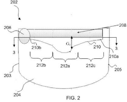
[0036] FIG. 2 illustrates one example inner wall or backstop that may be used to provide the above-described advantages. The golf club head 202 includes a rear 204, a hosel 206, a front face plate or ball striking surface 208, and an internal wall or backstop 210. In some examples, the ball striking surface 208 may be a separate portion connected to the golf club head 202 such as by fitting into a channel in the golf club head, a friction fit between walls of the golf club head 202, a mechanical fastener, and the like. Although the wall 210 is shown as a singled piece member, the wall 210 may be formed of two or more portions and may be connected using known means of connection, without departing from the invention.
[0037] As shown in FIG. 2, the internal wall or backstop 210 may be contoured, as will be discussed more fully below. The internal wall or backstop 210 may be formed of a lightweight material, such as a lightweight metal. Some example lightweight metals that may be used include steel, titanium and titanium alloys, aluminum and aluminum alloys, magnesium and magnesium alloys, etc. Additionally or alternatively, the inner wall or backstop 210 may be formed of any of these metal materials and/or from composite materials, such as carbon fiber composite materials, fiberglass composite materials, basalt fiber composite materials, polymer materials, etc. In still o
ther arrangements, the backstop 210 may be formed having a matrix structure, rather than as a solid wall, in order to further reduce weight associated with the backstop 210.[0038] In some examples, the backstop 210 may be fixed to the golf club head 202 at one or more ends 210a, 210b, such as with mechanical fasteners, screws, adhesives, and the like. In some examples, the ends 210a, 210b of the backstop 210 may be connected to the golf club head via screws formed of a composite material to reduce weight added to the golf club head 202. The fixed ends 210a, 210b of the backstop 210 may provide additional stiffness and structure to those points (e.g., points having greater or increased stress during flexing). The portion of the backstop 210 extending between each fixed end 210a, 210b might not be fixed to the golf club head 202, thereby allowing for at least some flexibility of the backstop 210, in some arrangements. The backstop 210 also may be formed, at least in part, as an integral structure with one or more of the parts of the club head body. For instance, the backstop 210 may be integrally formed with the club head body such that the ends 210a, 210b of the backstop 210 are integrally formed with the toe and/or heel of the golf club head. This arrangement may provide additional stiffening characteristics for the backstop 210. In some examples, the ball striking face may be connected to the golf club head body, integrally formed backstop, etc.
[0039] As shown in FIG. 2, the backstop 210 extends generally from a heel 203 of the golf club head 202 to the toe 205 and is positioned generally behind the front ball striking surface 208. That is, in this example structure 200, the backstop 210 is positioned within an interior void of the golf club head formed by the top, bottom, toe, heel, etc. of the golf club head 200, and may be positioned more toward a center of the golf club head 200 than the ball striking surface 208. The backstop 210 may be arranged behind the ball striking surface 208 such that a space or gap G.sub.1 exists between the ball striking surface 208 and the backstop 210 when the club head 202 is at rest (i.e., when a ball is not being struck by the ball striking surface 208). This gap G.sub.1 may allow for flex in the ball striking surface 208, or at least portions thereof, when a golf ball is struck by the ball striking surface 208 of the golf club head. As shown in FIG. 2, a size of the gap G.sub.1 may vary along a length of the inner wall or backstop 210 in the heel 203 to toe 205 direction. For instance, the size of the gap G.sub.1 may extend from 0.1 inches to 0.75 inches. This gap G.sub.1 and flexibility of the ball striking surface 208 will be discussed more fully below.
[0040] As mentioned above, the backstop 210 may have a contoured shape. For instance, the backstop 210 may be non-linear to allow for additional flexing of the ball striking surface 208 in some portions and to limit the amount of flexing of the ball striking surface 208 in other portions. For instance, the golf club head 202 may have an inner wall or backstop 210 having three regions, a central region 212a and two side regions, 212b, and 212c. The central portion of the region 212a may be arranged a greater distance from the ball striking surface 208 than at least one of end regions 212b, 212c of the backstop 210. The arrangement of FIG. 2 illustrates an inner wall or backstop 210 having a gradual or relatively shallow slope in the end regions 212b, 212c. This gradual slope may allow for the size of the gap G.sub.1 to gradually increase as the inner wall or backstop 210 extends from an end portion 210a, 210b toward the central region 212a. The central region 212a of the backstop 210 may have a steeper or more substantial slope to increase the size of the gap G.sub.1 in the central region. In some examples, the maximum gap G.sub.1 size along the length of the inner wall or backstop 210 will be positioned in the central region 212a. This increased distance between the backstop 210 and the ball striking surface 208 in the central region 212a may allow for greater flexibility of a corresponding central portion of the ball striking surface 208. Various other geometries (both linear and non-linear geometries) may be used without departing from the invention, as will be discussed more fully below.
[0041] In some instances, computer modeling applications may be used to determine an optimal geometry of the backstop 210. For instance, computer modeling may be used to determine a desired or optimal shape to provide an appropriate COR response, etc., e.g., based on an individual’s typical or dominant ball contact location on the ball striking face 208 surface. In some arrangements, the backstop 210 shape or geometry may be customized to a particular player, swing, swing speed, etc. using computer modeling.
.
.
.
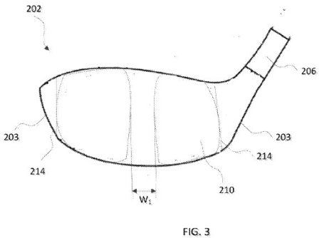
[0043] FIG. 3 is a cross sectional view of the golf club head 202 of FIG. 2 taken along line 3-3. The hosel 206 and backstop 210 are shown from a front view. The golf club head 202 may include internal supports 214 arranged near a toe 205 and a heel 203 of the golf club head 202. The internal supports 214 may provide a structure to which the ends 210a, 210b of the backstop 210 may be connected to the golf club head 202. For instance, the ends 210a, 210b of the backstop 210 may be connected to the internal supports 214, such as via threaded fasteners or other mechanical fasteners, welds, adhesives, and the like. As discussed above, connecting the ends 210a, 210b of the backstop 210 to the golf club head 202 may provide increased stiffness at the ends to aid in maintaining the position of the backstop 210 when contacted by the front ball striking surface 208 when a golf ball is struck. The width of the central region W.sub.1 is illustrated as relatively constant along the height of the backstop 210. However, in some examples, the width W.sub.1 of the central region may vary along the height of the backstop 210. In some examples, this width W.sub.1 may be between 0.2 and 1.2 inches wide.
.
.
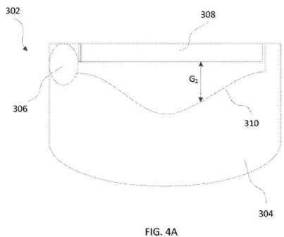
.[0045] FIGS. 4A and 4B illustrate one example arrangement of a contoured inner wall or backstop and flexible ball striking surface. The golf club head 302 includes a rear 304, a hosel 306, a ball striking surface 308 and an inner wall or backstop 310. Similar to the arrangement of FIG. 2, a gap G.sub.2 is present between the ball striking surface 308 and the backstop 310. Also similar to the arrangement of FIG. 2, the contour of the backstop 310 provides for a gradual increase of the gap G.sub.2 as the backstop extends from an end point, that may be connected to the golf club head 302, toward a central portion of the backstop 310. FIG. 4A illustrates the golf club head 302 in an at rest position. Accordingly, the ball striking surface 308 is generally planar.
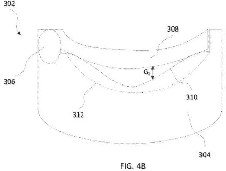
[0046] FIG. 4B illustrates the example golf club head 302 as it strikes a golf ball (not shown). As the golf club head 302 strikes the golf ball, the ball striking surface 308 may flex inward, toward the backstop 310, thereby reducing the size of the gap G.sub.2. As the ball striking surface 308 flexes inward, portions of the ball
striking surface 308 may contact the backstop 310 which may reduce or prevent additional flexing of the ball striking surface 308 or that portion of the ball striking surface 308. For instance, as shown in FIG. 4B, the end regions of the ball striking surface 308 contact the portions of the backstop 310 closer to the ball striking surface 308. Accordingly, the backstop may reduce or prevent additional flexing in those areas. However, the contour of the backstop 310 may allow additional flexing in the central portion of the ball striking surface 308, due to the greater distance between the ball striking surface 308 and the backstop 310 (i.e., greater gap distance G.sub.2) in the central region or portion.[0047] Line 312 represents the potential flex of the ball striking surface 308 without the presence of the backstop 310. Without the backstop 310, the ball striking surface 308 may flex more than it would with the backstop 310 present, which may result in greater stress on the material of the ball striking surface 308 and thus increased likelihood of cracking, fatigue, failure, etc. This arrangement including the backstop 310 may maintain the COR response of the club head within USGA limits, and may prevent overflexing of the ball striking surface 308 which may result in damage, such as cracking, breaking, and the like.
.
.
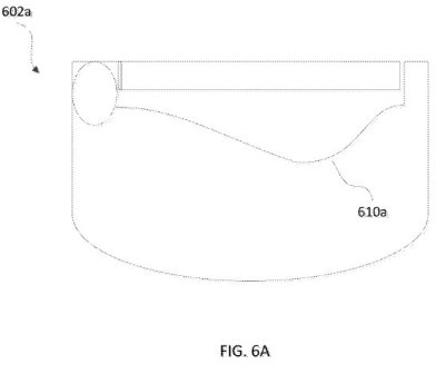
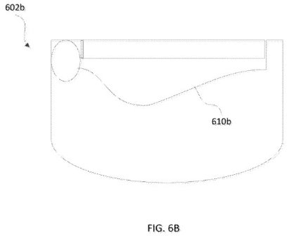
.[0054] Further, the shape, contour, etc. of the interior wall or backstop of one or more arrangement described herein may be customized for a particular user’s swing. For instance, the deepest portion of the wall or backstop may be offset to accommodate a user with a slice, hook, etc. For instance, FIGS. 6A and 6B illustrate alternate backstop arrangements with backstops 610a and 610b having the deepest portion offset from a center of the backstop.
Place you bets; will this ever make it into an actual product? How much extra would you pay for the customization aspect?
David Dawsey – Keeping an Eye on Golf Ball Patent Applications