
Did You Know That the Markings on Your Golf Ball Can Control the “Orbit of the Head, Ballistic Trajectory or Impact Point”
Yes, these must be some pretty special golf ball markings to control the “orbit of the head, ballistic trajectory or impact point.” Let’s see if see if you buy it!
The patent issued today to SRI Sports (parent of the Srixon brand) as USPN
Golf ball 2 shown in FIG. 1A and FIG. 1B has a group 4 of marks. The group 4 of marks is printed on the surface of the ball. The group 4 of marks is provided on one site on the golf ball 2. Although not shown in the figures, the group 4 of marks is printed on a paint layer of the ball. The group 4 of marks may be covered by a clear paint layer. The group 4 of marks should be visually observed. Printing of the group 4 of marks may be carried out by a known procedure such as pad printing or thermal transfer.
Although not shown in the figures, the golf ball 2 has numerous dimples. Constitution of the dimples is similar to those of conventionally known golf balls. In Figures attached hereto, illustration of the dimples is omitted.
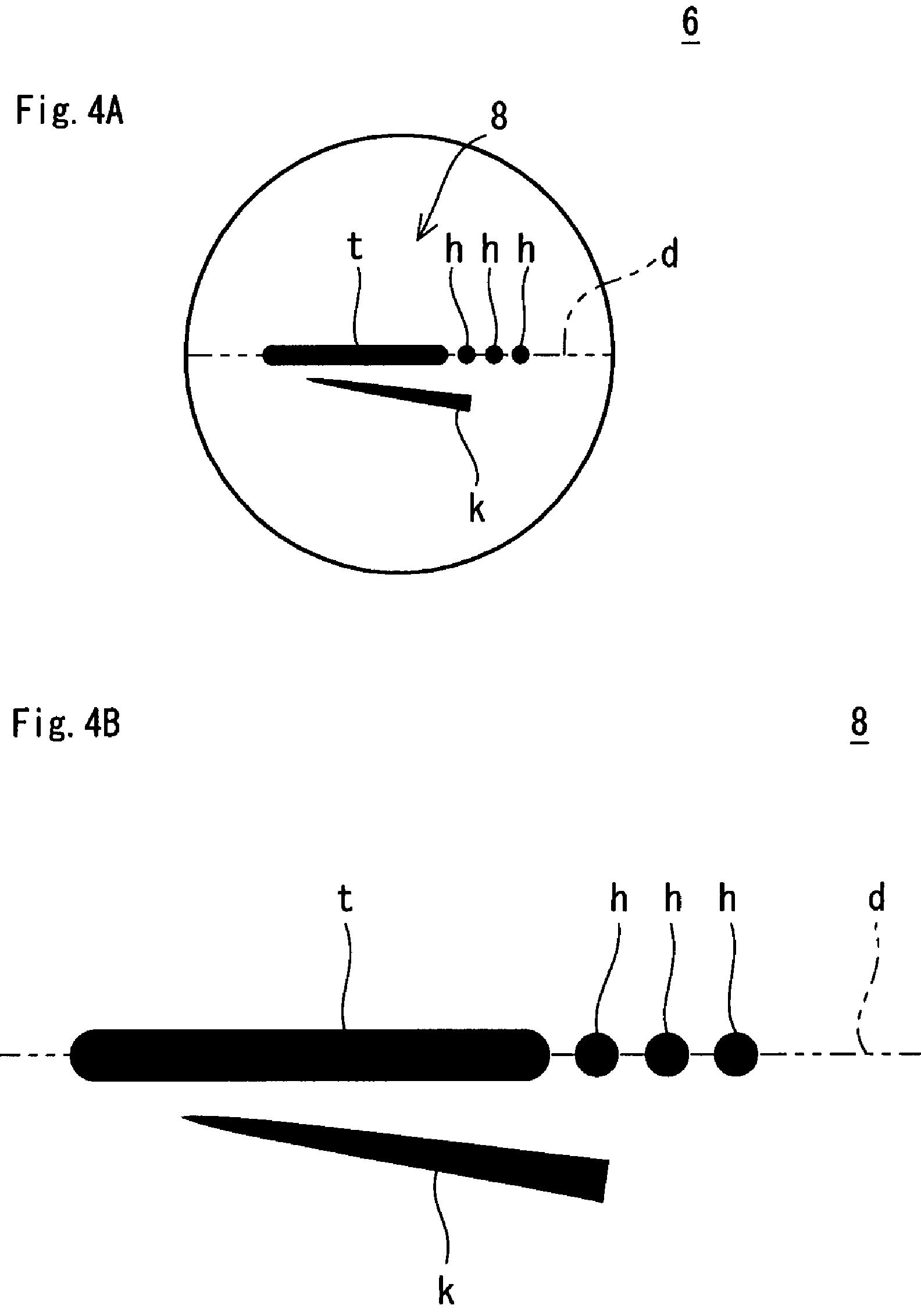
FIG. 1B shows an enlarged view of the group 4 of marks. The group 4 of marks includes multiple marks. The group 4 of marks includes a target mark t, inclined marks k, and accompanied marks h. The target mark t, the inclined marks k, and the accompanied marks h are visible at one view. The target mark t, the inclined marks k, and the accompanied marks h are provided in an area which can be seen at once from one point of view. Upon the address, the golf player can see the target mark t, the inclined marks k, and the accompanied marks h at one view.
Because the golf ball 2 has a spherical shape, it has a great circle. The great circle refers to a circle on the surface of the sphere yielded by allowing a plane that passes to cross the center of the sphere. In the present invention, the great circle refers to a circle on the surface of the golf ball yielded by allowing a plane that passes to cross the center of the golf ball. In one golf ball, the great circles are present in uncountable numbers.
The target mark t may be single or multiple marks provided along one great circle d. In the embodiment shown in FIG. 1A, the target mark t has a linear shape. The target mark t is present on great circle d. The target mark may be an aggregate of dot marks. The multiple dot marks constituting the target mark t are aligned on a substantially straight line along one great circle d. The linear target mark t appears to be a substantially straight line. A substantially straight target line is imaged by the target mark t. The ball may be placed with the target line to direct toward the intended direction, and then addressing can be executed based on this target line. Upon the address, orientation of the face can be adjusted based on the target line.
The inclined mark k is a mark which appears to be inclined with respect to the target mark. The group 4 of marks includes two inclined marks k. The inclined marks k are provided on the left and right sides of the target mark t. Only one inclined mark k may be provided on either one side or another side of the target mark t. The inclined mark k may be an aggregate of dot marks (separate dot marks). The dot marks constituting the inclined mark k are aligned on a substantially straight line along a line inclined with respect to the great circle of the target mark.
The accompanied mark h is a mark provided on the same great circle d on which the target mark t is provided. In the group 4 of marks, three accompanied marks h are provided. In the group 4 of marks, the accompanied marks h are provided on one side of an extended line along the great circle d (FIG. 1B, right side). The accompanied mark may be also provided on one side and another side of an extended line along the great circle d. The accompanied marks h have a dot shape. The accompanied mark h has a circular shape. By thus making the accompanied marks h to have a dot shape, effect achieved by the accompanied mark h described later is improved.
.
.
.
Typical method of use of the golf ball according to the present invention will be explained. The golf ball according to the present invention is effective in occasions in which golf players can place the ball with a setting of the direction optionally selected such as tee shots and puttings.
Upon tee shots, the ball is placed such that the target mark t faces on the upper side, and the target line is directed toward the intended direction. The golf player addresses based on this target line. For example, the addressing may be executed so that the face surface orientation agrees with the direction of the target line. The target line is, as described above, a line imaged by the target mark. The target line agrees, on the plan view, with the great circle d that runs along the target mark t.
Next, a shot is made while looking at the inclined mark k, the side mark s or the accompanied mark h. Accordingly, the following “Effect due to Inclined Mark k”, “Effect due to Side Marks” or “Effect due to Accompanied Mark h” can be achieved.
[Effect Due to Inclined Mark k]
When a swing is made such that the head moves along any inclined mark k, the orbit of the head will be outside-in or inside-out. For example, a case is envisaged in which a right-handed golf player addresses and hits the golf ball 2 in the state of permitting the group 4 of marks to be visible as shown in FIG. 1A. In this case, the target is present on the left-hand side of FIG. 1A, and the ball is hit to be oriented to the left-hand direction of FIG. 1A. Upon the hitting, outside-in ballistic trajectory is apt to be achieved when the swing is made so as to move the head along the first inclined mark ka among two inclined marks k. The outside-in ballistic trajectory is likely to result in a slice or fade ball flight. Inside-out ballistic trajectory is apt to be achieved when the swing is made so as to move the head along the second inclined mark kb. The inside-out ballistic trajectory is likely to result in a hook or draw ball flight.
Hence, the orbit of the head can be controlled by the inclined mark k. Desired ballistic trajectory can be achieved by the inclined mark k. For the golf players who are troubled over excess slice or hook, the inclined mark k can be of assistance in correction of the excess slice or hook.
What is indicated by a symbol theta in FIG. 1B is an angle formed between the great circle d along the target mark t, and the mid line k1 in the cross direction of the inclined mark k. In light of the improvement of the effect to control the orbit of the head, the angle .theta. is preferably equal to or greater than 1 degree, more preferably equal to or greater than 2 degrees, and particularly preferably equal to or greater than 3 degrees. In light of prevention of achieving excess outside-in or inside-out ballistic trajectory, and improvement of control performance of the ballistic trajectory, the angle .theta. is preferably equal to or less than 30 degrees, more preferably equal to or less than 20 degrees, and particularly preferably equal to or less than 10 degrees. This angle theta can be an angle on the aforementioned plan view.
Have your doubts about this? Just ask Mr. A and Mr. B.
Hereinafter, advantages of the present invention will be explained by way of Examples, however, the present invention should not be construed as being limited based on the description of the Examples. For reference, the size such as distance and the angle described below were measured on the plan view set out in the foregoings.
Example 1
A golf ball of Example 1 was obtained by printing the group 4 of marks shown in FIG. 1A on a commercially available golf ball. The color of the group of marks was black. The length L1 of the target mark t was 18 mm; the length L2 of the inclined mark k was 17 mm; the distance L3 from the front end of the target mark t to the rear end of the accompanied mark h which is positioned the farthest from the target mark t was 26 mm; and the angle .theta. was 7.5 degrees (see, FIG. 1b. The accompanied mark h had a diameter of 1.7 mm, and the target mark t had a thickness of 2.0 mm.
[Evaluation]
Evaluation was made by two testers, Mr. A, and Mr. B. Mr. A and Mr. B were characterized as in the followings. Both Mr. A and Mr. B were right-handed.
[Mr. A]
Dominate ball; fade
head speed (in use of driver): 37 m/s
[Mr. B]
Dominate ball; draw
head speed (in use of driver): 43 m/s
Evaluation Method
Example 1
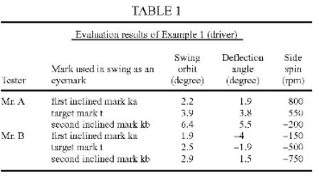
The golf ball of Example 1 was evaluated as follows. First, the ball was placed so that the target mark t faced the upper side, while the target line was directed toward the intended direction. Next, each tester addressed based on this target line. Each tester addressed so that the face surface orientation agreed with the direction of the target line. Each tester addressed in the state of permitting the group 4 of marks to be visible as shown in FIG. 1A. Thus addressed golf player hit the golf ball 2 shown in FIG. 1A. The target was present on the left-hand side of FIG. 1A, and the ball was hit to be oriented to the left-hand direction of FIG. 1A. Each tester swung the club while looking at any mark among the group 4 of marks. The results of this evaluation are shown in Table 1 below. The test was carried out using a driver (W#1). The results of evaluation using the driver are shown in Table 1 below.
[Driver Used in Evaluation]
Mr. A used ALL NEW XXIO (loft: 11 degrees, shaft item number: MP400, shaft flex: R) as a driver. Mr. B used ALL NEW XXIO (loft: 9 degrees, shaft item number: MP400, shaft flex: S) as a driver.
[Swing Orbit]
“Swing Orbit” means the angle in the right-left direction of the orbit of the head immediately before the impact with respect to the intended direction. The swing orbit indicates the degree of outside-in, or inside-out. A camera was set just above the point P where the ball was placed in the addressing. When the club head passed two positions, i.e., 3 cm and 9 cm to the impact point respectively, the photoflash was lighted to take pictures by the camera from above. By thus taking pictures, image data were obtained having two head images at the moment of lighting of the flash. An angle .alpha. (degree) formed by the intended direction and a line drawn between the two images was analyzed based on the image data. This angle .alpha. (degree) is shown in Tables below in the column of “Swing orbit”. The angle .alpha. is an angle in the horizontal direction. The angle .alpha. is represented by a plus (+) value in the case of inside-out ballistic trajectory, while it is represented by a negative (-) value in the case of outside-in ballistic trajectory.
.
.
.
As is clear from the results in the above Tables, the balls hit while looking at the first inclined mark ka in Example 1 attained the ballistic trajectory more approximate to be outside-in as compared with the balls hit while looking at the target mark t. In addition, the balls while looking at the second inclined mark kb in Example 1 attained the ballistic trajectory more approximate to be inside-out as compared with the balls hit while looking at the target mark t.
So, do I buy it? The answer is a cautious “probably,” but the last thing I need on the tee box is one more thing that I am trying to remember. Which line should I be staring at?
David Dawsey – Keeping an Eye on Golf Ball Inventions
PS – click HERE to read more interesting golf ball patent posts