
A Window Inside the Future of Nike Irons? Nike Air Irons Would Get Some Attention
Over the past two and a half years I have posted a couple of times (here and here ) about Nike’s fluid filled iron designs. Well, last week another Nike
[0021] Aspects of this invention relate to golf club heads and golf clubs including such club heads. Golf club heads according to at least some example aspects of this invention may include: (a) a club head body including a ball striking face, the club head body defining a rear cavity opposite the ball striking face; (b) a fluid-filled bladder at least partially located within the rear cavity (and optionally adjacent to and/or in contact with a rear surface of the ball striking face); and (c) a retaining member engaged with the club head body, the retaining member at least partially holding the fluid-filled bladder within the rear cavity. If desired, the club head further may include one or more of: (a) a window opening defined in and/or a window element engaged with the retaining member (e.g., wherein at least a portion of the fluid-filled bladder is adjacent, exposed through, and/or visible through the window opening or element); (b) a bridge member, e.g., extending along a portion of an exterior surface of the retaining member, optionally to help hold the retaining member and/or fluid-filled bladder in place with respect to the club head body; and/or (c) a weight member, e.g., engaged with the retaining member, engaged with the club head body, engaged with the fluid-filled bladder, provided in an chamber defined in the restraining member, provided in the fluid-filled bladder, etc.
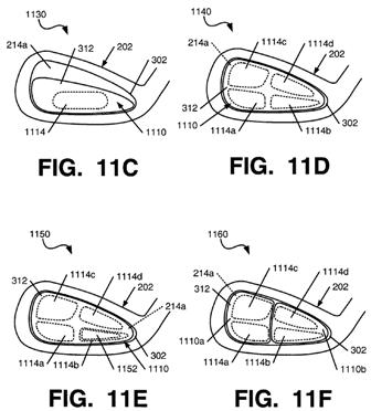
[0022] Golf club heads in accordance with additional and/or alternative aspects of this invention may include: (a) a club head body including a ball striking face, the club head body defining a rear cavity opposite the ball striking face; and (b) an insert member at least partially located within the rear cavity and engaged with the club head body, wherein an interior surface of the insert member includes a club head body engaging structure and defines one or more chambers facing a rear surface of the ball striking face. In at least some examples of the invention, the one or more chambers will collectively cover at least 30% of a total surface area of the interior surface of the insert member. In some more specific examples, if desired, the one or more chambers will collectively cover at least 50%, 75%, 85%, 90% or even 95% of the total surface area of the interior surface of the insert member. Additionally or alternatively, if desired, in at least some examples of this invention, the one or more chambers may collectively cover at least 30% of a total interior major surface area of the rear cavity, or even 50%, 75%, 85%, 90%, or 95% of the total interior major surface area of the rear cavity. The insert member may cover all, substantially all (e.g., at least 95%), most (e.g., at least 50%), or any desired portion of the interior major surface area of the rear cavity.
[0023] If desired, one or more of the chambers in the insert member in accordance with these example aspects of the invention further may include a fluid-filled bladder member at least partially contained therein. Also, club head structures in accordance with these example aspects of the invention further may include one or more of: a window opening defined in and/or a window element engaged with the insert member; a bridge member, e.g., extending along a portion of an exterior surface of the insert member, optionally to help hold the insert member in place with respect to the club head body; and/or a weight member, e.g., engaged with the insert member, engaged with the club head body, engaged with the fluid-filled bladder, provided in an chamber defined in the insert member, provided in the fluid-filled bladder, etc.
.
.
.
.
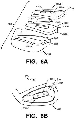
[0033] As illustrated in FIGS. 3B and 3C, this example golf club head structure 104 includes a fluid-filled bladder member 306 (in this example structure 104, a gas-filled bladder member 306). The gas-filled bladder member 306 of this illustrated example includes an exterior envelope structure 306a that defines an interior chamber 306b that may be filled with fluid, such as gas. The bladder 306 may be made of any desired materials, formed in any desired manner (e.g., polymeric materials formed by blow molding, etc.), without departing from this invention. As some more specific examples, the bladder 306 may be made from resilient, thermoplastic, elastomeric barrier films, such as polyester polyurethanes, polyether polyurethanes (such as cast or extruded ester based polyurethane films, e.g., Tetra Plastics TPW-250); thermoplastic urethanes, such as PELLETHANE™ (a product of the Dow Chemical Company of Midland, Mich.), ELASTOLLAN® (a product of the BASF Corporation), and ESTANE® (a product of the B. F. Goodrich Co.), all of which are either ester or ether based); thermoplastic urethanes based on polyesters, polyethers, polycaprolactone, and polycarbonate macrogels; thermoplastic films containing crystalline material, such as those disclosed in U.S. Pat. Nos. 4,936,029 and 5,042,176 to Rudy, each of which is entirely incorporated herein by reference; polyurethane including a polyester polyol, such as those disclosed in U.S. Pat. No. 6,013,340 to Bonk et al., which is entirely incorporated herein by reference; and/or multi-layer films formed of at least one elastomeric thermoplastic material layer and a barrier material layer formed of a copolymer of ethylene and vinyl alcohol, such as those disclosed in U.S. Pat. No. 5,952,065 to Mitchell et al., which also is entirely incorporated herein by reference. Gas-filled bladder materials and/or members of the types used in “AIR” type footwear products and/or other footwear products commercially available from NIKE, Inc. of Beaverton, Oreg. also may be used as gas-filled bladder 306 without departing from this invention.[0034] Also, any gas or other fluid may be used to fill the interior chamber 306b of the bladder 306 without departing from this invention, including air, inert gases, liquids, etc. The filling gas or fluid may be under pressure, under vacuum, or under standard or atmospheric conditions without departing from this invention. If desired, the gas-filled bladder 306 may be sealed or vented to the atmosphere.
[0035] The gas-filled bladder 306 may be flexible, such that it readily conforms to the shape of the space into which it is fit, it may be somewhat conformable, it may be relatively rigid, such that it substantially holds its shape under applied force, or it may be very rigid. Such rigidity/conformability features may depend on the overall structure of the bladder 306, such as its wall thicknesses; materials; molding structures or features; the presence or absence of support structures, e.g., molded into bladder 306, as separate elements, etc.; etc. Also, any number of independent chambers (optionally interconnected chambers) may be provided in a single gas-filled bladder 306 and/or any number of gas-filled bladders 306 may be provided in an overall club head structure 104 without departing from this invention.
[0036] The gas filled-bladder 306 may be used as a support or housing for other elements or structures of a golf club head 104. In this illustrated example, the gas-filled bladder 306 optionally contains a weight member 308 (e.g., a lead or tungsten containing structure). Of course, when present, these additional elements (such as weight members) may be provided at any desired positions and/or locations without departing from the invention. In the illustrated example, the weight member 308 is provided within the envelope 306a of the bladder 306. If necessary or desired, the weight member 308 (or other element) may be engaged with the envelope 306a, such as to an interior or exterior wall of the envelope 306a by cements or adhesives. As additional possibilities, component support structures may be provided in the envelope 306a or within the bladder 306 to support the weight member 308 (or other element). As still additional examples, if desired, the weight member 308 (or other element) may be engaged with the interior or exterior surface of the envelope 306a, such as by cements, adhesives, fusing techniques, mechanical connectors, retaining element structures, friction fits, etc., and/or they may be engaged with component support structures provided on the interior or exterior surfaces of the envelope 306a (and optionally extending somewhat into or out of the chamber 306b) without departing from this invention. Any desired way of engaging a weight member 308 (or other component) with, in, and/or on the gas-filled bladder structure 306 may be used without departing from this invention. Also, any number of weight members 308 (or other components) may be provided at any desired locations without departing from this invention, e.g., to affect the swing and/or ball flight characteristics associated with the club head 104 (to customize the club for a specific user or swing type, to provide a draw bias, to provide a fade bias, to provide a high trajectory bias, to provide a low trajectory bias, etc.).
.
.
.
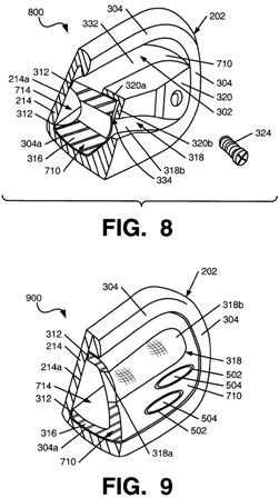
[0040] The retaining member 310 may include other features without departing from this invention. For example, as illustrated in FIGS. 3A through 3C, a window 318 may be defined in the retaining member 310, e.g., to allow one to see and/or to expose the interior chamber 314 of the retaining element 310 and/or the gas-filled bladder member 306. The window 318 may be provided in any desired manner without departing from this invention. For example, the window 318 may be integrally formed in the retaining member structure 310, e.g., by integrally providing a transparent or semi-transparent portion in the overall retaining member structure 310. As another example, the window 318 may be formed by providing a window opening 318a in the retaining element 310 structure (as illustrated in FIGS. 3A through 3C, at least a portion of the gas-filled bladder 306 in this example structure 104 lies adjacent the window opening 318a). While the window opening 318a may remain open, if desired, as another alternative, a window element 318b may be provided to at least partially cover (and optionally to completely cover) the window opening 318a. The window element 318b may be transparent, semi-transparent, translucent, variously colored, etc. without departing from this invention. Any desired material may be used for the window element 318b without departing from the invention, including polymeric materials.
That has the potential to be pretty cool, not to mention that it would be a neat piece of cross-branding.
David Dawsey – The Golf Attorney